
Photovoltaic system and boost converter thereof

a photovoltaic system and boost converter technology, applied in the direction of electric variable regulation, process and machine control, instruments, etc., can solve the problem of how to reduce greenhouse gas emission, which has become a major international problem

Inactive Publication Date: 2011-06-16
DU PONT APOLLO
View PDF5 Cites 133 Cited by
  • Summary
  • Abstract
  • Description
  • Claims
  • Application Information

AI Technical Summary

Benefits of technology

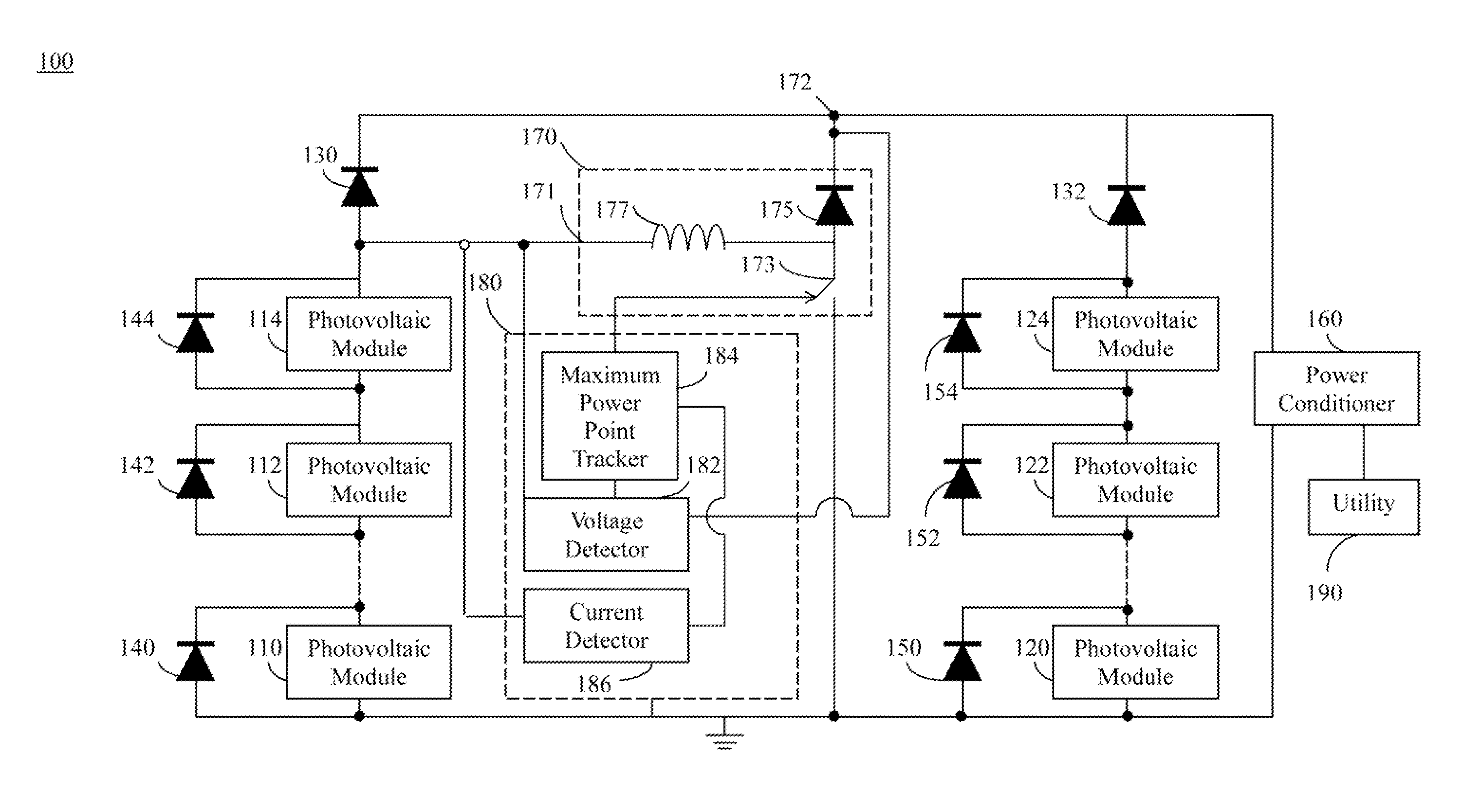
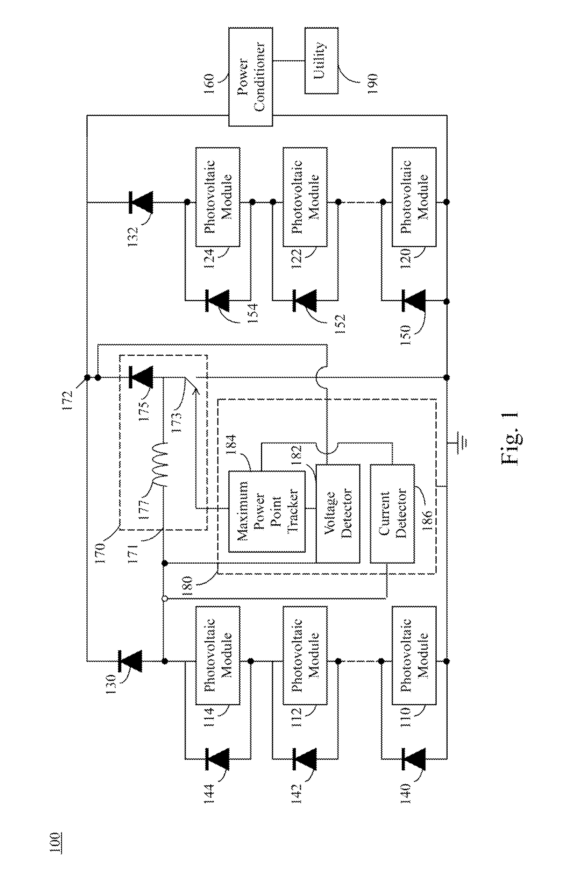
[0009]According to another embodiment of the present invention, a boost converter includes a controlled switch, a diode, an inductor and a controller. An anode of the diode is connected to the controlled switch, and a cathode of the diode configured to serve as a voltage output terminal connected to a cathode of a blocking diode, wherein the blocking diode is connected in series with a string of photovoltaic modules. One end of the inductor is connected to the anode of the diode, and another end of the inductor is configured to serve as a voltage input terminal connected to a cathode of the blocking diode. In use, the controller can provide a pulse width modulation signal to control the controlled switch when the blocking diode is cut off.

Problems solved by technology

However, upon combustion, fossil energies produce greenhouse gas such as carbon dioxides, nitrogen oxides, sulfur oxides, and hydrocarbons that are detrimental to the environment.
Hence, how to reduce greenhouse gas emission has become a major international issue.

Method used


Image

  • Photovoltaic system and boost converter thereof
  • Photovoltaic system and boost converter thereof

Examples


Embodiment Construction

[0013]In the following detailed description, for purposes of explanation, numerous specific details are set forth in order to attain a thorough understanding of the disclosed embodiments. It will be apparent, however, that one or more embodiments may be practiced without these specific details. In other instances, well-known structures and devices are schematically shown in order to simplify the drawing.

[0014]As used in the description herein and throughout the claims that follow, the meaning of “a”, “an”, and “the” includes reference to the plural unless the context clearly dictates otherwise. Also, as used in the description herein and throughout the claims that follow, the terms “comprise or comprising”, “include or including”, “have or having”, “contain or containing” and the like are to be understood to be open-ended, i.e., to mean including but not limited to. As used in the description herein and throughout the claims that follow, the meaning of “in” includes “in” and “on” un...


PUM


Abstract

A photovoltaic system is disclosed herein, which includes a blocking diode, a string of photovoltaic modules, a boost converter and a controller. The photovoltaic modules are connected in series with the blocking diode. A voltage input terminal of the boost converter is connected to an anode of the blocking diode, and a voltage output terminal of the boost converter is connected to a cathode of the blocking diode. In use, the controller can drive the boost converter when the blocking diode is cut off.

Description

RELATED APPLICATIONS[0001]This application claims priority to U.S. Provisional Application Ser. No. 61 / 285,780, filed Dec. 11, 2009, which is herein incorporated by reference.BACKGROUND[0002]1. Technical Field[0003]The present disclosure relates to a photoelectric device, and more particularly, a photovoltaic system.[0004]2. Description of Related Art[0005]Energy is the source power of all economic activities and thus is highly relative to the economic advancement. For the time being, energy sources include fossil energies such as petroleum, natural gas, and coal, nuclear power, waterpower, terrestrial heat and solar energy. Among the above-mentioned energy sources, fossil energies are the most widely used energy with nuclear power being in second place, whereas the others are much less commonly used. However, upon combustion, fossil energies produce greenhouse gas such as carbon dioxides, nitrogen oxides, sulfur oxides, and hydrocarbons that are detrimental to the environment. Henc...

Claims


Application Information

Patent Timeline
Patent Type & Authority Applications(United States)
IPC IPC(8): H01L31/042G05F1/46
CPCG05F1/67Y02E10/58Y02B10/14Y02B10/10Y02E10/56
Inventor LEE, CHUN-HSIEN
Owner DU PONT APOLLO
Learn More