Power unit

a power unit and power supply technology, applied in hybrid vehicles, contact mechanisms, electric devices, etc., can solve the problems of increasing resistors are needed, and the cost of the circuit may be increased, so as to reduce the cost and the effect of safety

Inactive Publication Date: 2011-06-16
TOYOTA JIDOSHA KK
View PDF1 Cites 23 Cited by
  • Summary
  • Abstract
  • Description
  • Claims
  • Application Information

AI Technical Summary

Benefits of technology

[0012]The invention provides a power unit that enables the discharge of a high-voltage power from a smoothing capacitor even when no discharge command is issued by a control system, making ...

Problems solved by technology

However, in the described power unit, the control of the system main relay and the control of the discharge relay are required in the event of a collision.
However, an increase in the cost of the circuit may be entailed.
However, a large disch...

Method used


Image

  • Power unit
  • Power unit
  • Power unit

Examples


first embodiment

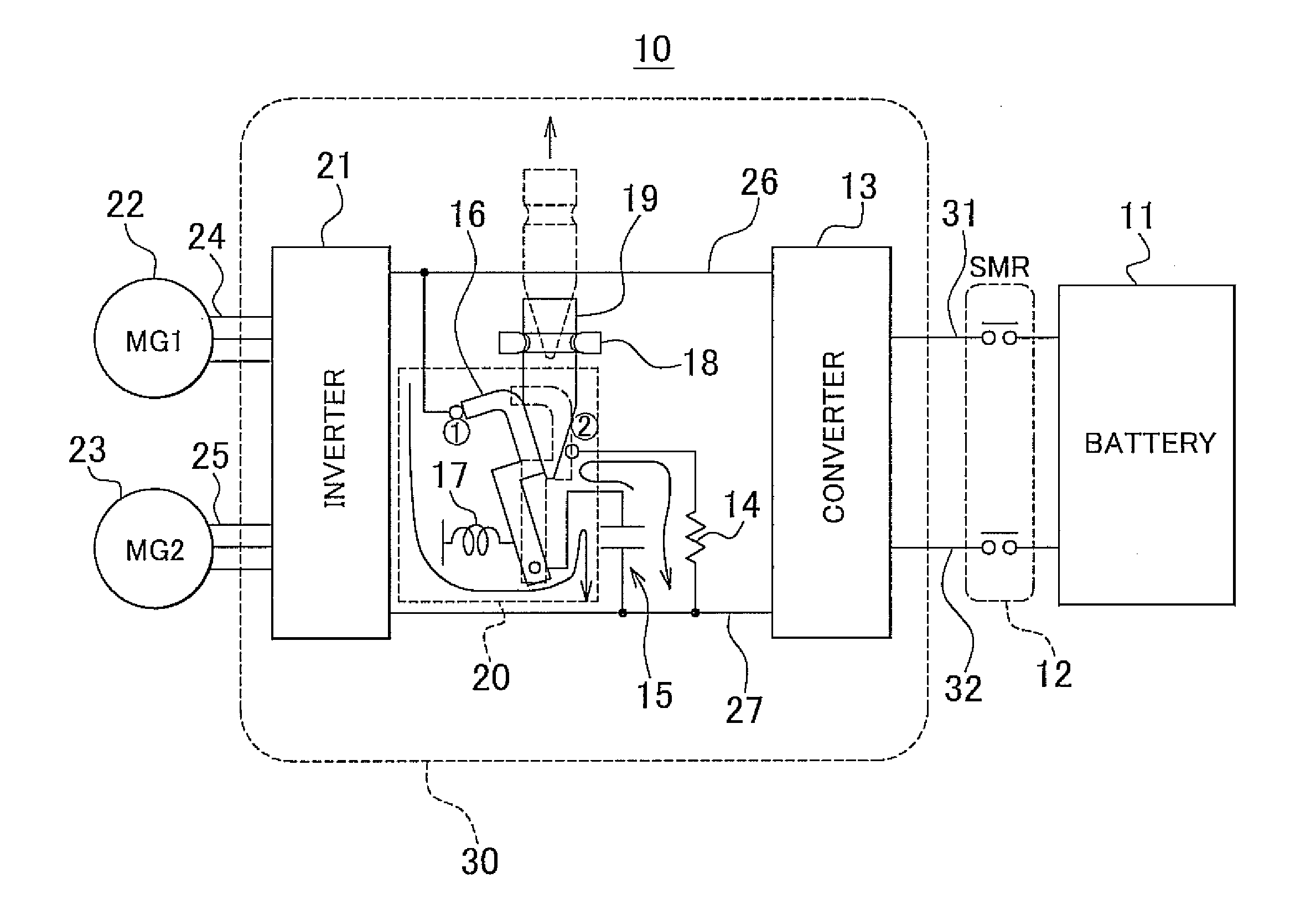
[0036]The coupling plate 45 of FIG. 5 supports the PCU 30 from behind, and slides on the guide plate 44 when the PCU 30 is pressed in the longitudinal direction from the front to the rear of the vehicle with a predetermined force. The PCU 30 is thereby displaced to disengage the insulating engagement rod 19 fitted in the discharge relay and thereby discharge residual electrical charge from the smoothing capacitor. While the employment of the coupling plate 45 makes it possible to set the press force leading to the operation of the discharge relay and to set the operation displacement amount of the discharge relay large, the employment of the coupling plate 45 may hinder a further simplification and reduction in the size of the fixation structure 2. Thus, as a modified example of the first embodiment, a slippage structure may be adopted in which the coupling plate 45 and the guide plate 44 are disused, instead, the mounting platform 49 is extended in the longitudinal direction from t...

second embodiment

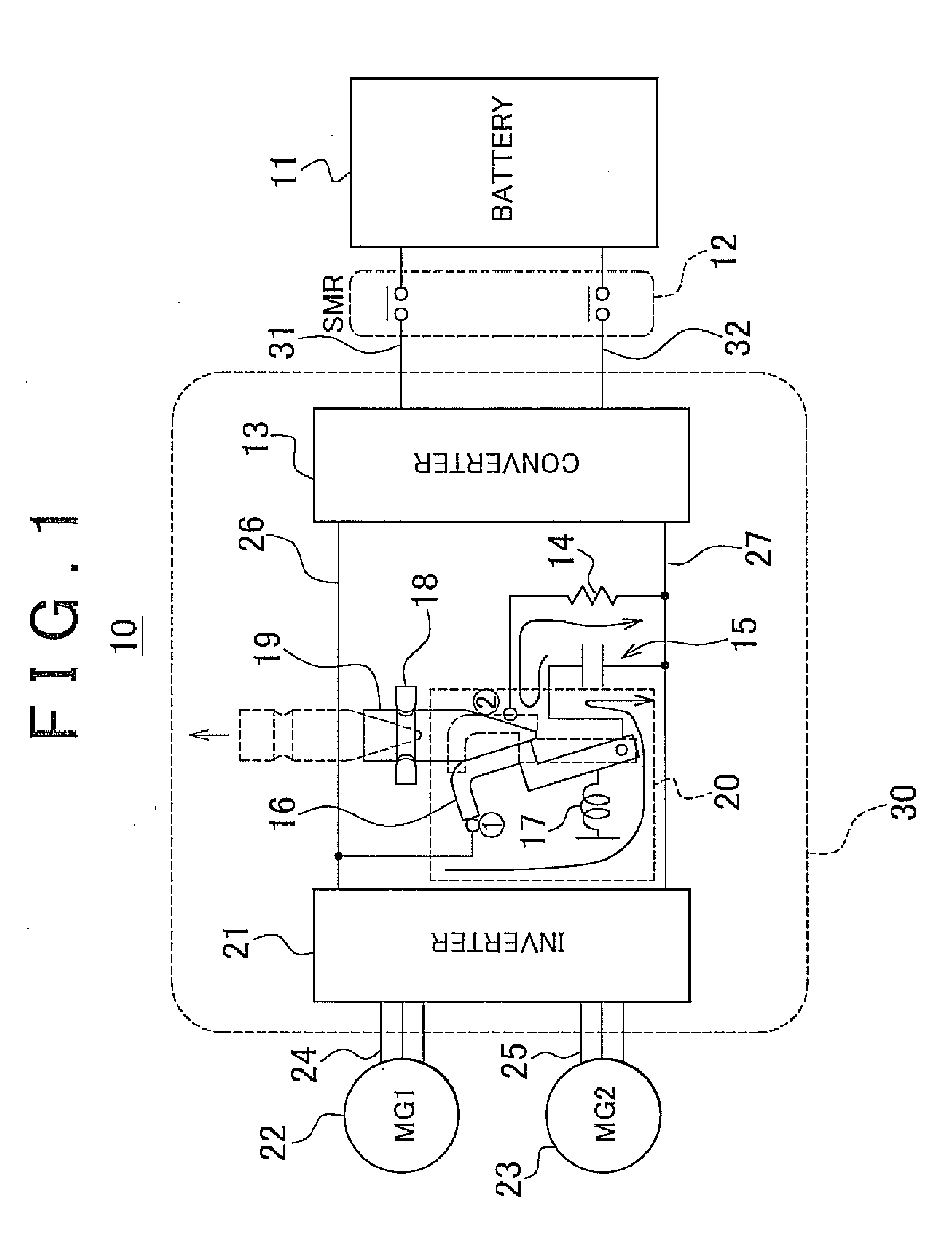
[0038]In contrast, FIG. 7 shows another embodiment that serves as a reference in understanding the invention. The power supply system 50 of FIG. 7 has a circuit in which the discharge relay 20 and the resistor 14 are connected in series with each other to discharge electrical charge remaining in the smoothing capacitor 15. The power supply system 50 discharges electricity from the smoothing capacitor 15 through the relay 20 after the SMR 12 is disconnected from the battery 11 by the control system. Therefore, a discharge resistor is indispensable in the event the SMR 12 cannot be disconnected from the battery.

[0039]As is apparent from the power supply system 40 of FIG. 6, the resistor 14 employed in the power supply system 10 of FIG. 1 in this embodiment of the invention may be omitted. Therefore, the size and cost of the power supply system may be further reduced.

[0040]As described above, by employing a power unit according to this embodiment of the invention, electricity may be di...


PUM


Abstract

In order to discharge electrical charges from a smoothing capacitor even if no discharge command is issued by a control system, making use of the displacement of a power unit in the event of a collision, a movable electrode is connected to a first contact connected to a high-potential bus, and the smoothing capacitor is connected with a converter and an inverter to be in parallel in the case where an engagement rod is positioned by a retaining ring. Further, when the engagement rod is disengaged from the retaining ring and removed from a relay, the movable electrode is held in contact with a second contact by a pressure spring, and the electrical charge remaining in the smoothing capacitor is discharged to a low-potential bus through a discharge portion.

Description

CROSS-REFERENCE TO RELATED APPLICATIONS[0001]The present application claims priority of Japanese Patent Application No. 2009-282751 filed on Dec. 14, 2009, which is incorporated herein by reference in its entirety including the specification, drawings and abstract.BACKGROUND OF THE INVENTION[0002]1. Field of the Invention[0003]The invention relates to a power unit for a vehicle, and more particularly, to a power unit that discharges electrical charge from a smoothing capacitor in the event of a collision of a vehicle.[0004]2. Description of the Related Art[0005]In recent years, vehicles such as hybrid vehicles, fuel-cell-powered vehicles and the like, each having a power train in which an engine or a fuel cell or the like combined with an electric motor, have been developed and put into practical use. In such hybrid vehicles, the direct-current power of a battery is converted into alternating-current power by an inverter and then supplied to an alternating-current motor to drive the...

Claims


Application Information

Patent Timeline
IPC IPC(8): H01H35/00
CPCB60L3/0007Y02T10/7241B60L3/04B60L11/123B60L11/14B60L11/1877B60L2210/40H01H35/14H02M2001/322Y02T10/6217Y02T10/7005Y02T10/7022Y02T10/705Y02T10/7077B60L3/0046B60L50/61B60L50/16B60L50/66Y02T10/62Y02T10/70Y02T10/7072Y02T10/72H02M1/322
Inventor ISHIGAKI, HIROSATO
Owner TOYOTA JIDOSHA KK
Why Eureka
Try Eureka