Method for generating two optical pulses with a variable, time pulse interval

a time-period interval and optical pulse technology, applied in the field of generating two delayed pulses, can solve the problems of frequent time delay, limited delay path with regard to its variability, and time delay, and achieve the effect of simplifying adjustmen

Active Publication Date: 2011-06-16
MENLO SYST
View PDF8 Cites 16 Cited by
  • Summary
  • Abstract
  • Description
  • Claims
  • Application Information

AI Technical Summary

Benefits of technology

[0011]Proceeding from this prior art, the object of the present invention is to provide a method for generating delayed pulses, with which the drawbacks to be found in the prior art can be overcome and, in particular, a simplified adjustment is made possible.

Problems solved by technology

In this case, a main problem consists in permanently adjusting the mechanical arrangement of the delay path and it is known from constructional systems in this regard that they frequently have to be readjusted.
Similar problems are produced here as in the previously mentioned prior art in that a mechanism, in this case a rotary mechanism, is required to adjust the delay path, which has to be very precise, and in that the delay path is limited with regard to its variability depending on the radius.
A limitation of the time delay is thereby produced in that the length of the delay path is limited by the size of the structure.
Because of the mechanisms used and the component geometries used, the variability of the delay paths in constructional systems of this type is also very limited.
With regard to the delay paths used, problems are also produced with regard to the readjustment and imprecisions due to vibrations at the structure, as with longer optical path lengths covered, the lateral deviations in the sense of the beam laws increase proportionally thereto.

Method used


Image

  • Method for generating two optical pulses with a variable, time pulse interval
  • Method for generating two optical pulses with a variable, time pulse interval
  • Method for generating two optical pulses with a variable, time pulse interval

Examples


Embodiment Construction

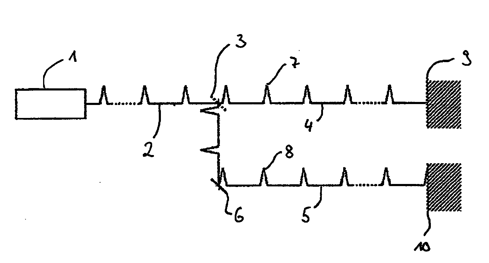
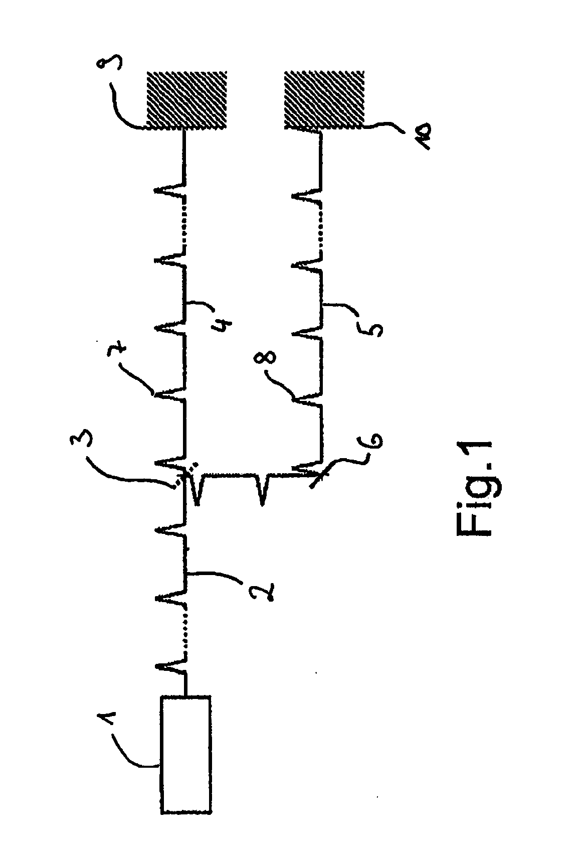
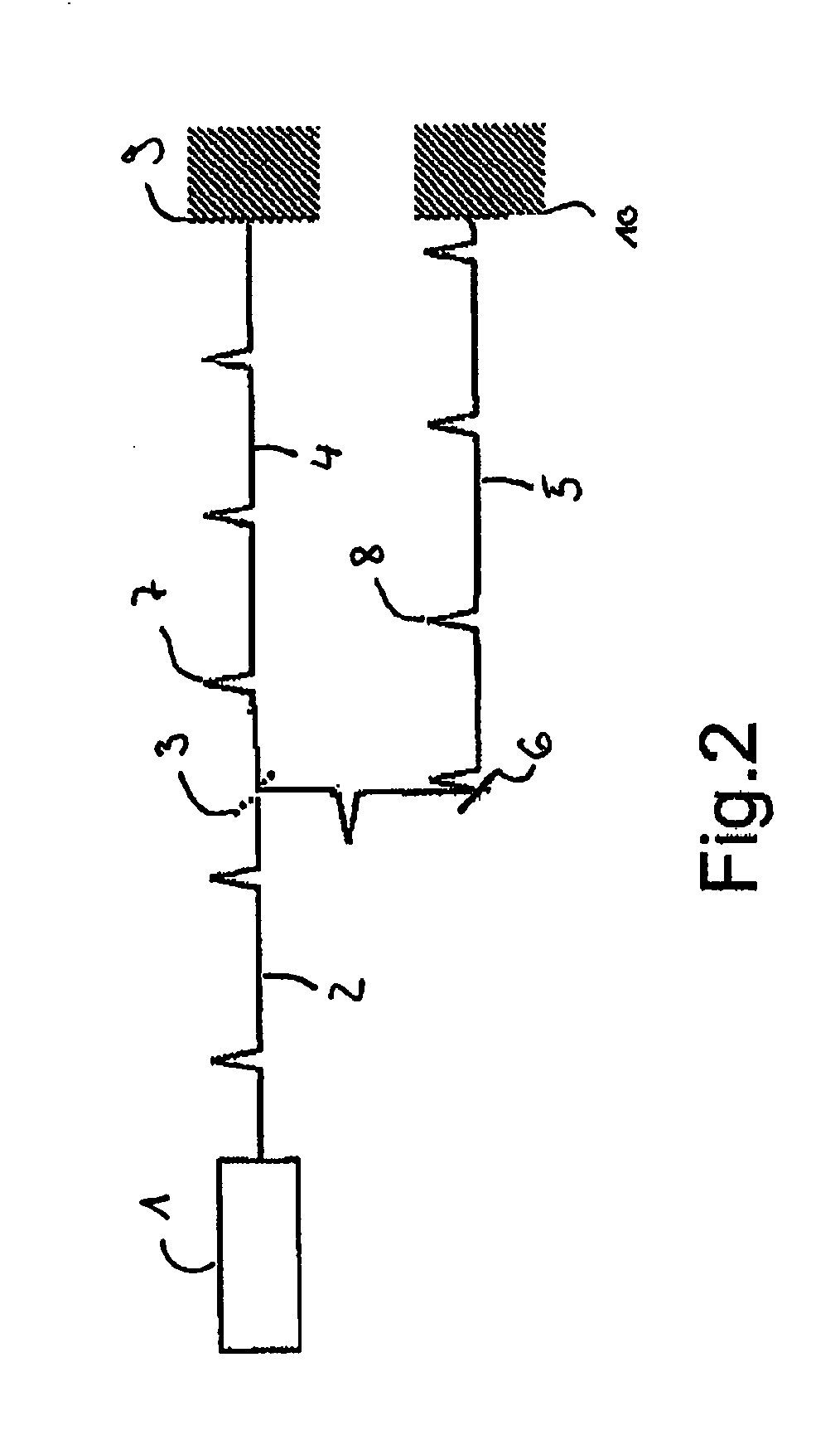
[0037]Referring to the drawings in particular, FIG. 1 shows an arrangement for carrying out the method according to the invention with a laser light source 1, which generates a pulsed beam 2, which impinges on a beam splitter 3 and is divided into a first partial beam 4 and a second partial beam 5. The second partial beam is deflected by means for beam deflection 6. The first partial beam 4 contains a first pulse 7, which is directed to a first target area 9. The second partial beam 5 contains a second pulse 8, which is directed to a second target area 10. The second partial beam 5 covers a delay path, which lies between the beam splitter 3 and the means for beam deflection 6. A pulse generated at a specific repetition rate is divided by a beam splitter 3, which may be configured here as a semi-permeable mirror, into a first pulse 7, which lies in a first partial beam 4, and into a second pulse 8, which lies in a second partial beam 5. In this case, the delay path is selected as a f...


PUM


Abstract

The invention relates to a method for generating two delayed pulses, in particular in terahertz spectroscopy and/or in pump-probe experiments, with the following method steps:
    • generating a pulsed beam using a beam source, in particular a pulsed laser;
    • dividing the pulsed beam, wherein a first partial beam contains a first pulse and a second partial beam contains a second pulse;
    • directing the two pulses onto a respective target area, wherein the first pulse directly reaches a first target area and the second pulse reaches a second target area after covering a delay path, and wherein the two target areas may coincide;
    • using the two pulses, in particular for a measuring method;
    • wherein a time delay of the two pulses in the respective target area is adjustable by means of a pulse repetition rate of the pulsed beam.

Description

CROSS REFERENCE TO RELATED APPLICATIONS[0001]This application is a United States National Phase application of International Application PCT / DE2009 / 000662 and claims the benefit of priority under 35 U.S.C. §119 of German patent application DE 10 2008 026 484.9 filed Jun. 3, 2008, the entire contents of which are incorporated herein by reference.FIELD OF THE INVENTION[0002]The present invention relates to a method for generating two delayed pulses, in which a time delay can be achieved without the use of mechanical parts and in which, in particular, the time delay can be varied in particular in terahertz spectroscopy and / or in pump-probe experiments, with the following method steps:[0003]generating a pulsed beam using a beam source, in particular a pulsed laser;[0004]dividing the pulsed beam, wherein a first partial beam contains a first pulse and a second partial beam contains a second pulse;[0005]directing the two pulses onto a respective target area, wherein the first pulse direct...

Claims


Application Information

Patent Timeline
Patent Type & Authority Applications(United States)
IPC IPC(8): G02B26/00
CPCG01N21/3581G01N21/636H01S3/10046H01S3/005H01S1/00H01S3/0057
Inventor HOCHREIN, THOMAS EUGENKOCH, MARTINKRUMBHOLZ, NORMAN
Owner MENLO SYST
Why Eureka
Try Eureka