Automatic measurement and gain control of distributed raman amplifiers

US20110141552A1Active Publication Date: 2011-06-16II VI DELAWARE INC +1

Image

  • Automatic measurement and gain control of distributed raman amplifiers
  • Automatic measurement and gain control of distributed raman amplifiers
  • Automatic measurement and gain control of distributed raman amplifiers

Examples


Embodiment Construction

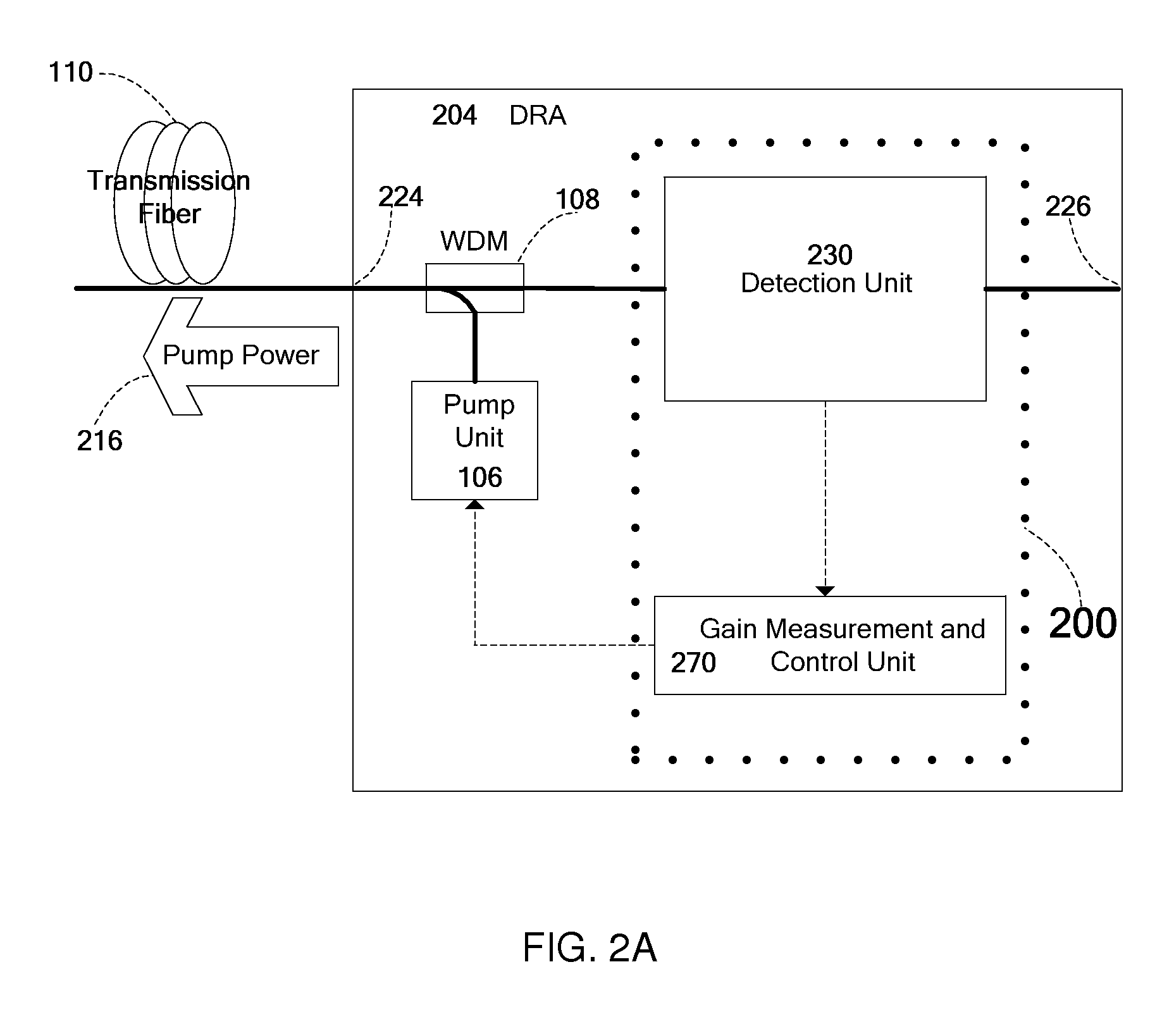
FIG. 2A shows schematically an apparatus for gain measurement and control in an embodiment of the invention, the apparatus marked as 200. As shown, apparatus 200 is included in a DRA 204 which may be either a forward or a backward DRA. As in known DRAs, DRA 204 includes a pump unit 106 and a WDM 108 to supply pump power 216 to transmission fiber 110. Apparatus 200 includes a detection unit 230 and a gain calculation and control (GCC) unit 270. Note that in some embodiments, apparatus 200 need not be physically located in the same physical enclosure as pump unit 106 and WDM 108. Detection unit 230 is configured to measure both before and during operation of the DRA, the optical power of a filtered component of the light entering DRA 204 via an input port 224 from a transmission fiber 110. As used herein, “during operation” refers to a state in which the Raman pumps are operational and a communication signal is being transmitted along the transmission fiber.

Detection unit 230 is coupl...


PUM


Abstract

Apparatus and method for gain measurement and control of a Distributed Raman Amplifier (DRA). Various embodiments of the apparatus include a detection unit operative to measure, during operation of the DRA, the optical power of a filtered component of the light entering the DRA from the transmission fiber and a gain calculation and control unit coupled to the detection unit and operative to calculate a signal Raman gain property from the measured optical power. The filtered component may exemplarily be a result of passing the light through a band pass filter, a spectral filter with a given spectral shape or a notch filter. The signal Raman gain property may be an average on-off signal Raman gain, an average net signal Raman gain or a signal Raman gain tilt within a communication band. The apparatus and method may be used to operate the DRA in Automatic Gain Control, i.e. to maintain a required constant signal Raman gain and / or signal Raman gain tilt.

Description

FIELDEmbodiments of the invention relate generally to optical fiber amplifiers used in fiber optics telecommunications systems and more particularly to distributed Raman amplifiers (DRAs).BACKGROUNDA modern optical communication system (also referred to herein simply as “system”) utilizes optical amplifiers to amplify wavelength division multiplexed (WDM) signal channels as they are transmitted through the system. The first optical amplifiers to be commercially deployed were Erbium doped fiber amplifiers (EDFAs), which are self-contained units placed between 60-120 km length spans of a communication link. These units contain a special Erbium doped fiber (EDF) which serves as the gain medium used to transfer energy from laser diode pumps within the units to the optical signal channels as they pass through the unit. These amplifiers are typically operated in Automatic Gain Control (AGC) mode, where a control loop measures the signal gain of the amplifier using input and output signal ...

Claims


Application Information

Patent Timeline
16 Jun 2011
Publication
US20110141552A1
IPC
H01S3/30
CPC
H01S3/1301; H01S3/302; H04B10/2942; H04B10/2916; H01S2301/04; H01S3/0078; H01S3/06754; H01S2301/02
Inventors
GHERA, URI; SHLIFER, ALEX