Condenser microphone and method for manufacturing the same

a condenser microphone and condenser technology, applied in the direction of electrical transducers, transducer types, piezoelectric/electrostrictive transducers, etc., can solve the problems of power module parts, noise generation, and microphone cables are vulnerable to extraneous noise (electromagnetic waves), so as to enhance the shielding effect and prevent cavity resonance.

Inactive Publication Date: 2011-06-16
AUDIO-TECHNICA
View PDF6 Cites 6 Cited by
  • Summary
  • Abstract
  • Description
  • Claims
  • Application Information

AI Technical Summary

Benefits of technology

[0016]According to the present invention, since the sealant agent having electric conductivity is filled in a void between the microphone cable in which the shielding wire is exposed and the support pipe, the electric conduction between the shielding wire and the support pipe is made more reliable, and the shielding effect can be enhanced further. Also, even if metal powder and the like are produced, since the sealant agent is filled, there is no fear that the metal powder drops into the power module part. Further, since the void of the support pipe is filled with the sealant agent, cavity resonance can also be prevented.

Problems solved by technology

Since sound signals are sent imbalancedly in the portion of microphone cable, the microphone cable is vulnerable to extraneous noise (electromagnetic waves).
That is, if strong electromagnetic waves are applied to the microphone cable, a high-frequency current intrudes into the unit part and the power module part, and noise is generated.
In particular, with the recent widespread use of cellular phones, such a trouble occurs often when a cellular phone is used in the vicinity of the microphone, which poses a big problem.
Unfortunately, the condenser microphone disclosed in Japanese Patent Application Publication No. 2006-33216 has problems described below.
Since the flexible pipe is capable of being flexed, both of the position and the number of contact points between the support pipe and the shielding wire are unspecified, so that differences in shieldability among individual microphone cables are liable to occur.
The metal powder drops into the power module part, which may cause a short-circuit accident.
Further, since the flexible pipe consists of a combination of steel wires and copper wires, rusting takes place due to a potential difference between dissimilar metals, and the rust may exert an influence on the shieldability.
Besides, since the interior of the support pipe is a cavity, sounds pass through the interior of the support pipe and intrude into the microphone unit, so that noise due to cavity resonance may be generated.

Method used


Image

  • Condenser microphone and method for manufacturing the same
  • Condenser microphone and method for manufacturing the same
  • Condenser microphone and method for manufacturing the same

Examples


Embodiment Construction

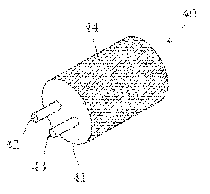
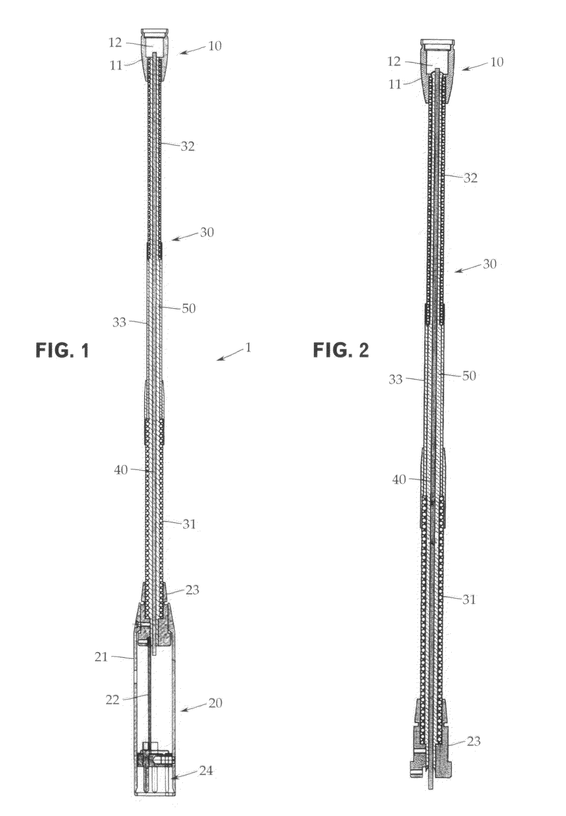
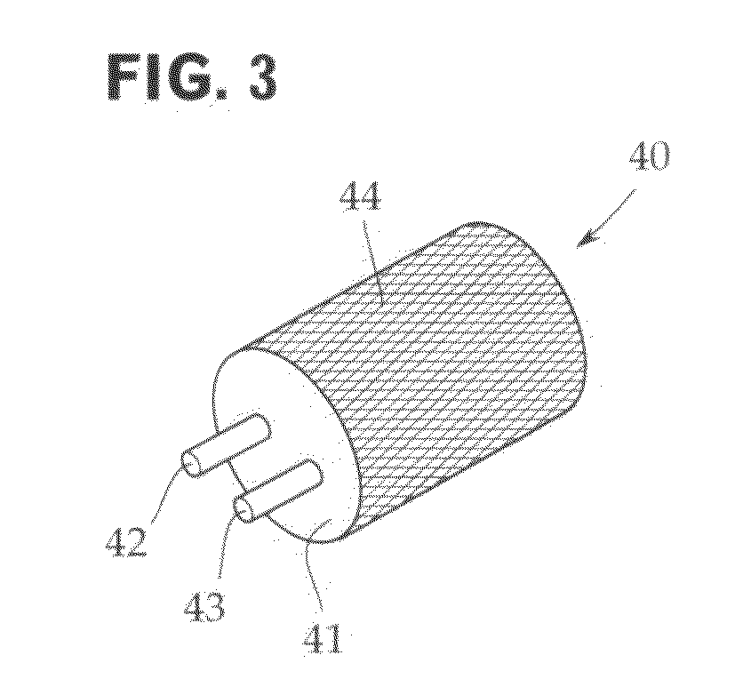
[0020]An embodiment of the present invention will now be described with reference to the accompanying drawings. The present invention is not limited to this embodiment. As shown in FIG. 1, a condenser microphone 1 includes a condenser microphone unit 10, an output module part (power module part) 20, and a support pipe 30 for supporting the condenser microphone unit 10.

[0021]The condenser microphone unit 10 has a cylindrical shield casing 11 formed of, for example, brass, and a microphone capsule 12 is mounted in the tip end portion of the shield casing 11.

[0022]Although not shown, a diaphragm and a backplate are contained in the microphone capsule 12 in an opposed state. As a polarization material, an electret may be used. Although not shown similarly, a field effect transistor (FET) serving as an impedance converter, electrically connected to the backplate, is housed in the shield casing 11.

[0023]The output module part 20 has a cylindrical shield casing 21 that is also used as a su...


PUM

PropertyMeasurementUnit
flexibleaaaaaaaaaa
conductiveaaaaaaaaaa
sizeaaaaaaaaaa

Abstract

There is provided a gooseneck condenser microphone that is further strengthened the shield structure of a support pipe and is less prone to causing a trouble. This condenser microphone has a support pipe 30 for supporting a condenser microphone unit 10 and an output module part 20, a microphone cable 40 in which a shielding wire 44 is exposed is inserted in the support pipe 30, and a conductive sealant agent 50 is filled in a void between the microphone cable 40 and the support pipe 30.

Description

CROSS-REFERENCE TO RELATED APPLICATION[0001]The present application is based on, and claims priority from, Japanese Application Serial Number JP2009-281193, filed Dec. 12, 2009, the disclosure of which is hereby incorporated by reference herein in its entirety.TECHNICAL FIELD[0002]The present invention relates to a gooseneck condenser microphone provided with a condenser microphone unit at the tip end of a support pipe including a flexible pipe and, more particularly, to strengthening of a shield structure in a support pipe part.BACKGROUND ART[0003]For example, as described in Japanese Patent Application Publication No. 2006-33216, in a gooseneck condenser microphone, a microphone unit is attached to the distal end of a support pipe in which a flexible pipe is used partially, and a connector terminal incorporating a power module for the microphone unit is provided on the rear end side of the support pipe.[0004]This gooseneck microphone is configured so that the direction of the micr...

Claims


Application Information

Patent Timeline
Patent Type & Authority Applications(United States)
IPC IPC(8): H04R11/04H04R31/00
CPCH04R11/04Y10T29/49005H04R31/00
Inventor AKINO, HIROSHI
Owner AUDIO-TECHNICA
Why Eureka
Try Eureka