Adiabatic multi-band RF pulses for selective signal suppression in magnetic resonance imaging

a magnetic resonance imaging and selective signal technology, applied in the field of magnetic resonance systems, can solve the problems of insufficient signal suppression, serious reduction of saturation efficiency, artifacts in most mr experiments, etc., and achieve the effect of suppressing magnetic resonance signals

Active Publication Date: 2011-06-16
THE JOHN HOPKINS UNIV SCHOOL OF MEDICINE
View PDF9 Cites 36 Cited by
  • Summary
  • Abstract
  • Description
  • Claims
  • Application Information

AI Technical Summary

Benefits of technology

[0012]Some embodiments of the current invention provide a magnetic resonance imaging (MRI) system, comprising: a magnetic resonance imaging scanner comprising: a main magnet providing a substantially uniform main magnetic field B0 for a subject under observation; and a radio frequency (RF) coil configured to irradiate a radio frequency (RF) pulse into a region of interest of the subject under observation, wherein the RF pulse comprises a base pulse comprising an adiabatic pulse having a first bandwidth time product (BWTP), wherein the RF pulse selectively suppresses magnetic resonance signals from more than one chemical component or more than one spatial region within the region of interest of the subject under observation, and wherein the adiabatic pulse is characterized by an amplitude modulation function and a frequency modulation funct

Problems solved by technology

Thus, combinations of B1 and B0 inhomogeneity can seriously reduce the saturation efficiency.
In high field magnets, this can be a serious problem, because localized shimming with higher-order shim coils will create more B0 inhomogeneity outside the volume-of-interest (VOI).
The resulting insufficient suppression of signals from around the VOI is likely to lead to artifacts in most MR experiments, commonly referred to as outer volume signals.
In short, the utility of these pulse sequences at B0 field strengths of 3 T and higher is often hampered by problems arising from power-deposition and B1 inhomogeneity.
Further, the solution of using a large coil does not address issues of outer volume signal suppression or susceptibility (e.g., metal implants in knees and

Method used


Image

  • Adiabatic multi-band RF pulses for selective signal suppression in magnetic resonance imaging
  • Adiabatic multi-band RF pulses for selective signal suppression in magnetic resonance imaging
  • Adiabatic multi-band RF pulses for selective signal suppression in magnetic resonance imaging

Examples


Embodiment Construction

[0028]Some embodiments of the current invention are discussed in detail below. In describing embodiments, specific terminology is employed for the sake of clarity. However, the invention is not intended to be limited to the specific terminology so selected. A person skilled in the relevant art will recognize that other equivalent components can be employed and other methods developed without departing from the broad concepts of the current invention. All references cited herein are incorporated by reference as if each had been individually incorporated.

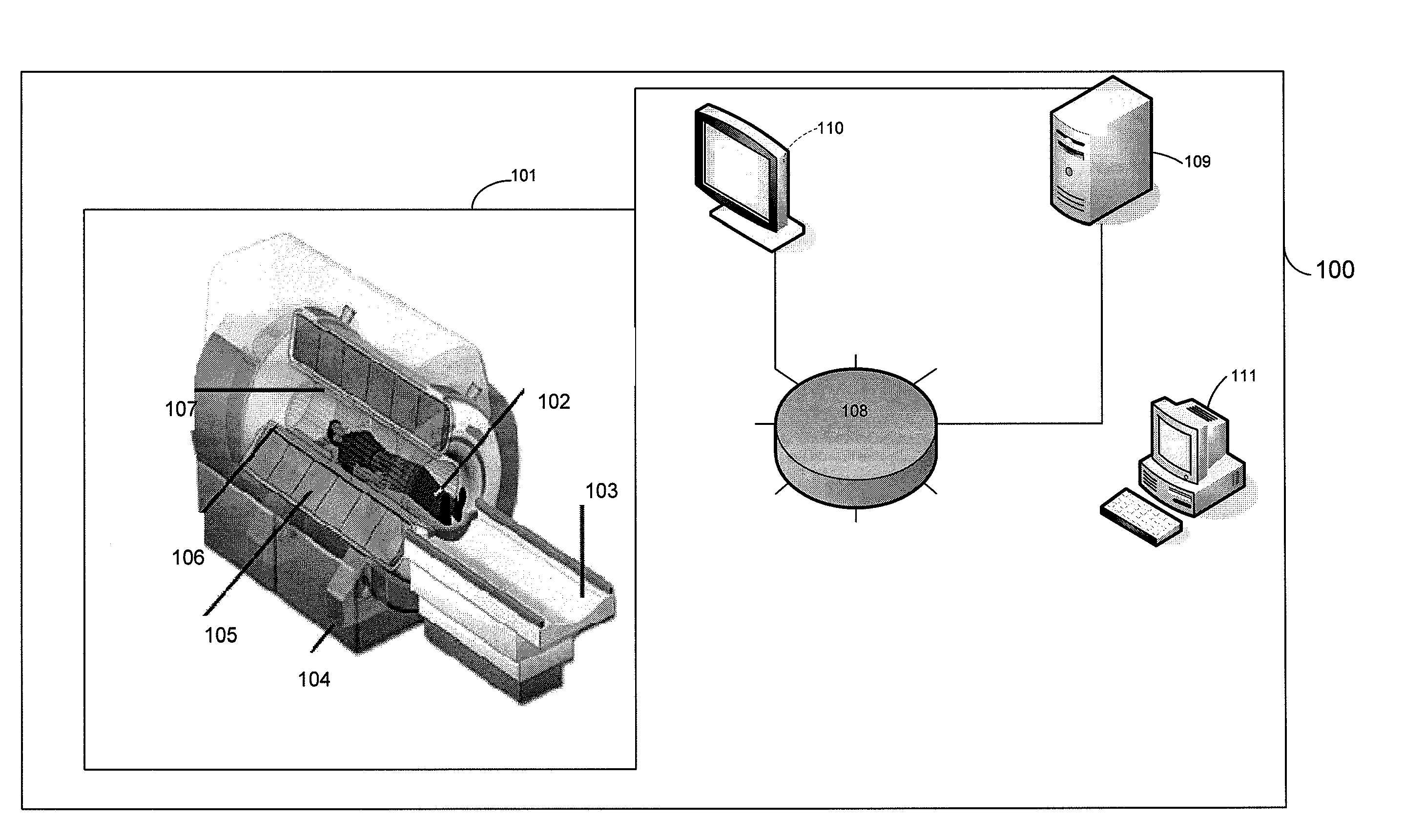
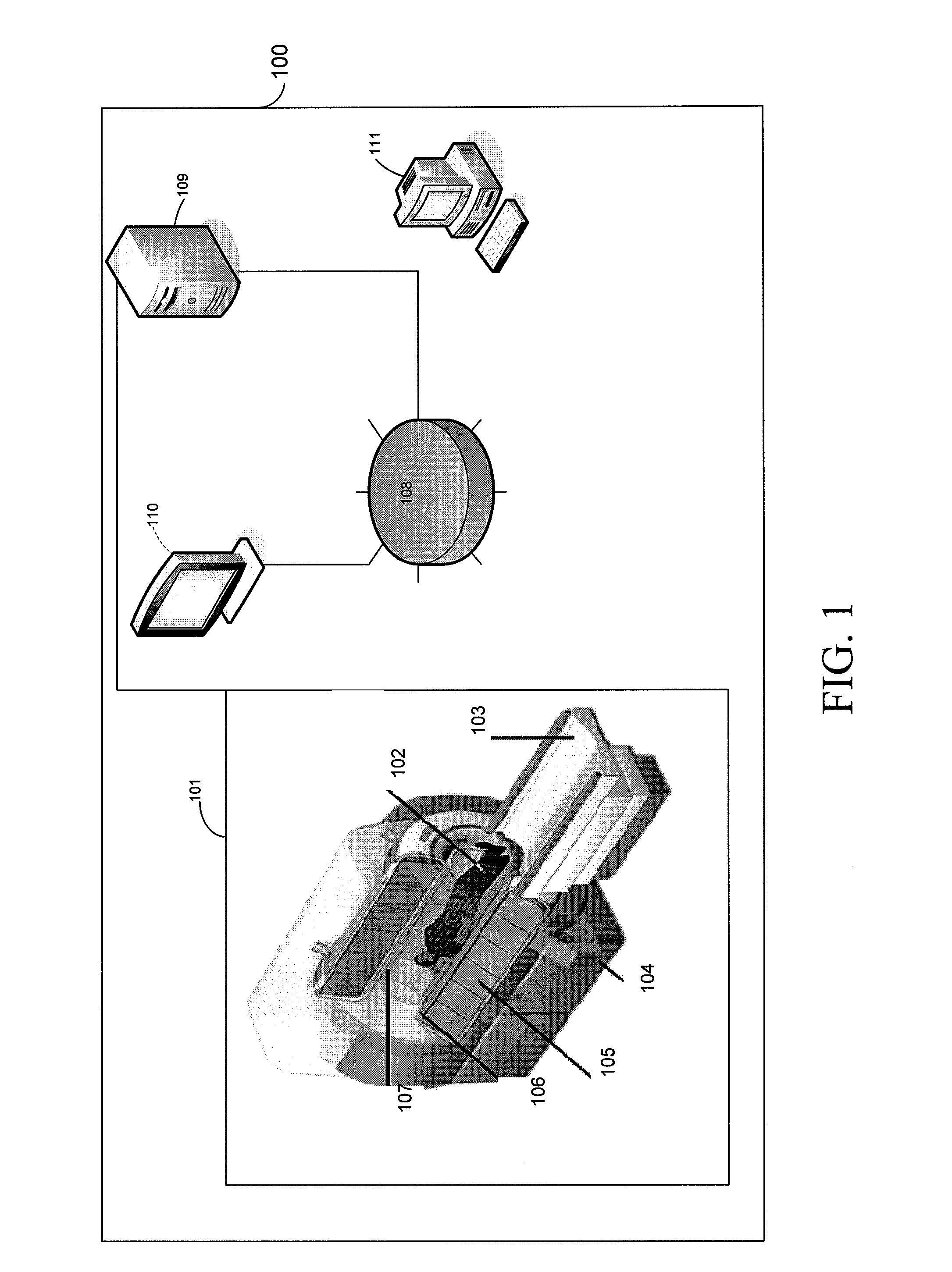
[0029]FIG. 1 is a schematic illustration of a magnetic resonance imaging (MRI) system 100 according to an embodiment of the current invention.

[0030]The MRI system 100 includes a magnetic resonance scanner 101, a data storage unit 108, and a signal processing unit 109. Magnetic resonance scanner 101 has a main magnet 105 providing a substantially uniform main magnetic field B0 for a subject 102 under observation on scanner bed 103, a g...


PUM


Abstract

A magnetic resonance imaging (MRI) system, comprising: a magnetic resonance imaging scanner comprising: a main magnet providing a substantially uniform main magnetic field B0 for a subject under observation; and a radio frequency (RF) coil configured to irradiate a radio frequency (RF) pulse into a region of interest of the subject under observation, wherein the RF pulse comprises a base pulse comprising an adiabatic pulse having a first bandwidth time product (BWTP), wherein the RF pulse selectively suppresses magnetic resonance signals from more than one chemical component or more than one spatial region within the region of interest of the subject under observation, and wherein the adiabatic pulse is characterized by an amplitude modulation function and a frequency modulation function.

Description

CROSS-REFERENCE OF RELATED APPLICATION[0001]This application claims priority to U.S. Provisional Application No. 61 / 088,374 filed Aug. 13, 2008, the entire contents of which are hereby incorporated by reference.[0002]The U.S. Government has a paid-up license in this invention and the right in limited circumstances to require the patent owner to license others on reasonable terms as provided for by the terms of Grant No.: R01CA100184, R21CA095907, P41RR15241 and R01RR015396 awarded by the National Institutes of Health.BACKGROUND[0003]1. Field of Invention[0004]The current invention relates to magnetic resonance systems and more particularly to systems that provide adiabatic pulses.[0005]2. Discussion of Related Art[0006]Selective signal suppression is required in many Magnetic Resonance Imaging (MRI) and Magnetic Resonance Spectroscopy (MRS) scans. Usually the desired frequency-selection profile is made up of an excitation band with a constant effective flip-angle, flanked by transit...

Claims


Application Information

Patent Timeline
IPC IPC(8): A61B5/055
CPCA61B5/055
Inventor OUWERKERK, RONALD
Owner THE JOHN HOPKINS UNIV SCHOOL OF MEDICINE
Why Eureka
Try Eureka