Method and system for regenerating particulate filter

a technology of particulate filter and regenerative system, which is applied in the direction of machine/engine, separation process, electric control of exhaust gas treatment, etc., can solve the problem of difficult expansion of heat contained in exhaust gas at optional times, achieve effective burning of matter trapped, increase the amount of oxygen, and increase the flow rate of compressed air

Inactive Publication Date: 2011-06-23
IHI CORP
View PDF7 Cites 18 Cited by
  • Summary
  • Abstract
  • Description
  • Claims
  • Application Information

AI Technical Summary

Benefits of technology

[0012]The method and system for regenerating a particulate filter according to the present invention can increase the amount of oxygen supplied to the particulate filter by increasing the flow rate of compressed air without depending on the flow rate of exhaust gas flowing across a turbine of a turbocharger, and delivering part of the compressed air to the particulate filter, bypassing the internal combustion engine, and thus, enables effective burning of matter trapped on the particulate filter. Particularly, if the compressed air bypassing the internal combustion engine is delivered to the exhaust line, immediately after the internal combustion engine, it can cause burning of unburned fuel, resulting in an increase in heat.
[0013]Further, regulation to reduce the energy loss that the exhaust gas suffers in the turbine, or in other words, regulation to reduce heat loss by reducing the work done by the exhaust gas in the turbine leads to an efficient rise in exhaust gas temperature.

Problems solved by technology

However, for efficient operation of the engine, the amount of fuel supplied to the engine is controlled to meet a predetermined air-fuel ratio, so that increasing heat contained in the exhaust gas at optional times is difficult.

Method used


Image

  • Method and system for regenerating particulate filter
  • Method and system for regenerating particulate filter
  • Method and system for regenerating particulate filter

Examples


first embodiment

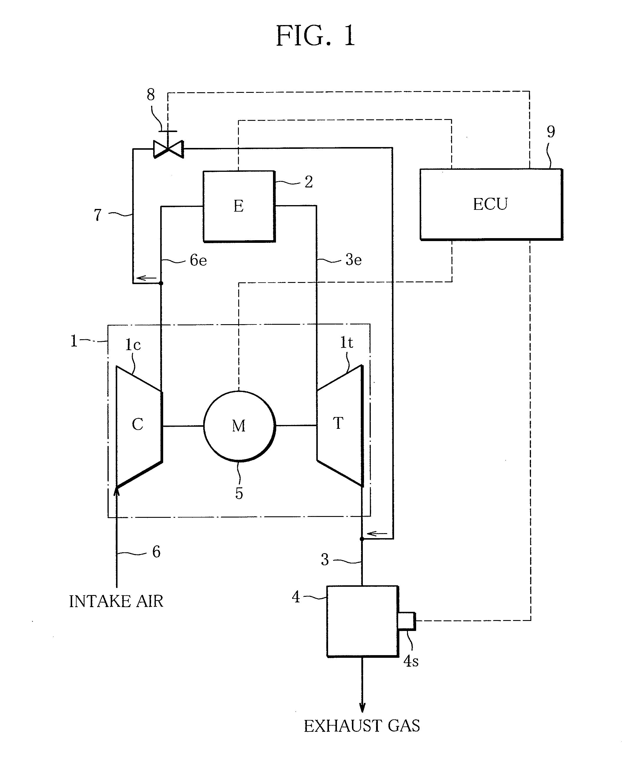
[0022]Referring to FIGS. 1 to 8, embodiments of the present invention will be described. FIG. 1 is a diagram schematically showing a configuration of particulate filter regeneration system according to the present invention.

[0023]The particulate filter regeneration system according to the present invention shown in FIG. 1 is designed to regenerate a particulate filter 4 arranged in an exhaust line 3 of an engine (internal combustion engine) 2 equipped with a turbocharger 1 by raising the temperature of exhaust gas, thereby burning matter trapped on the particulate filter 4 at times that the particulate filter 4 requires regeneration, and comprises an electric motor 5 functioning as an intake quantity regulation means capable of increasing the flow rate of compressed air without depending on the flow rate of exhaust gas flowing across a turbine 1t of the turbocharger 1, a bypass line 7 connecting a section of an intake line upstream of the engine 2 (an engine intake line 6e) to a sec...

second embodiment

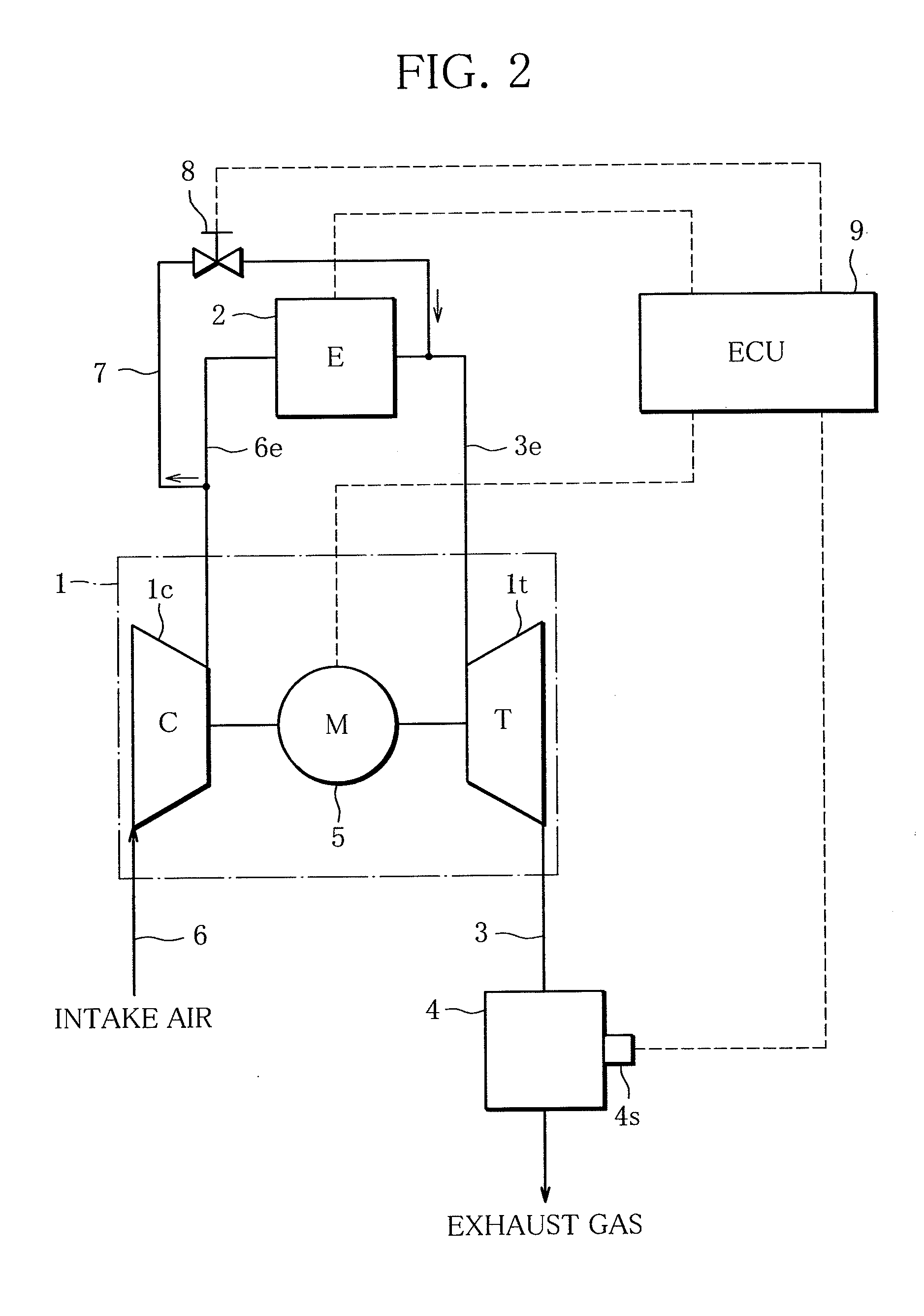
[0037]In the present invention shown in FIG. 2, the outlet of the bypass line 7 is connected to the engine exhaust line 3e. It is desirable that the outlet of the bypass line 7 be connected to the engine exhaust line 3e, immediately after the engine 2. Connecting the bypass line 7 at this position enables burning of unburned fuel in the engine exhaust line 3e, resulting in an increase in heat contained in exhaust gas (exhaust gas energy). In this case, part of the compressed air bypassing the engine is consumed to burn unburned fuel. Thus, the degree to which the flow rate regulation valve 8 is opened is controlled taking account of such consumption.

third embodiment

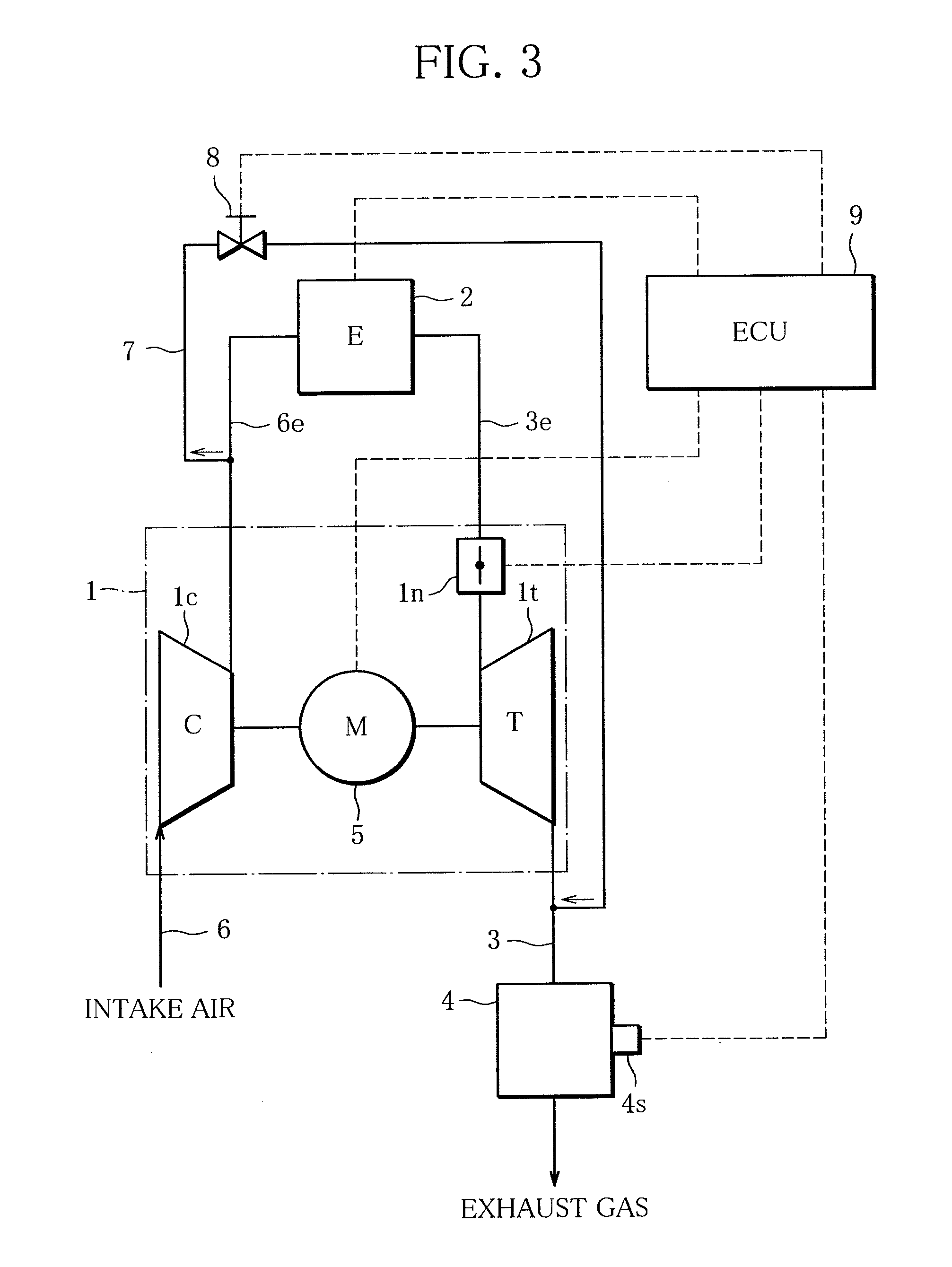
[0038]In the present invention shown in FIG. 3, the turbocharger 1 has a turbine flow regulation means regulating the flow rate of exhaust gas entering the turbine 1t, and the control means 9 regulates the turbine flow regulation means to reduce the energy loss that the exhaust gas suffers in the turbine 1t. In the illustrated example, the turbine flow regulation means consists of a variable nozzle 1n which makes the turbocharger 1a so-called variable displacement turbocharger. The variable displacement turbocharger can control the flow velocity or flow rate of exhaust gas entering the turbine 1t by opening and closing the variable nozzle 1n, thereby controlling the flow rate of compressed air delivered to the engine 2.

[0039]Such variable displacement supercharge 1 can, by itself, cover a wide range of engine 2 operation and provide high supercharging efficiency. The term “variable nozzle 1” is used to encompass all the variable mechanisms which can make the turbocharger 1a variable...


PUM

PropertyMeasurementUnit
mass ratioaaaaaaaaaa
temperatureaaaaaaaaaa
flow rateaaaaaaaaaa

Abstract

A particulate filter regeneration system regenerates a particulate filter provided in an exhaust line of an engine equipped with a turbocharger by burning matter trapped on the particulate filter by raising the temperature of exhaust gas at times that the particulate filter requires regeneration. The system has an electric motor functioning as an intake quantity regeneration portion capable of increasing the flow rate of compressed air without depending on the flow rate of exhaust gas flowing across a turbine of the turbocharger, a bypass line connecting an engine intake line upstream of the engine to a section of the exhaust line upstream of the particulate filter, a flow rate regulation valve regulating the flow rate in the bypass line, and a control portion controlling the electric motor and the flow rate regulator.

Description

TECHNICAL FIELD[0001]This invention relates to a method and system for regenerating a particulate filter provided to remove particulate matter from exhaust gas, specifically a method and system for regenerating a particulate filter by burning matter trapped on the particulate filter.BACKGROUND ART[0002]Most of automobiles using an internal combustion engine, such as a diesel engine or the like, are equipped with a particulate filter designed to clean up exhaust gas by trapping PM (particulate matter) in the exhaust gas. Particulate filters used in diesel engine automobiles are called DPFs, in particular. Since PM accumulated to a certain level clogs such DPFs, the DPFs are regenerated by burning PM by raising the temperature of exhaust gas (see Patent Document 1, for example).[0003]As mentioned above, in order to regenerate particulate filters such as DPFs, raising the exhaust gas temperature, namely increasing heat contained in the exhaust gas by supplying fuel to the engine is req...

Claims


Application Information

Patent Timeline
Patent Type & Authority Applications(United States)
IPC IPC(8): F01N3/023F01N3/05
CPCB01D46/0005Y02T10/47B01D46/42B01D2277/20B01D2279/30F01N3/023F01N3/0296F01N3/32F01N5/04F01N9/002F01N2270/00F01N2610/08F02B37/168F02B37/18F02B37/24F02B39/10Y02T10/144Y02T10/16B01D46/0063Y02T10/12Y02T10/40B01D46/84
Inventor SHIMIZU, MASAHIROSHINAGAWA, KAZUHIKO
Owner IHI CORP
Why Eureka
Try Eureka