
Waste heat driven desalination process

Inactive Publication Date: 2011-06-23
BL TECH INC
View PDF14 Cites 78 Cited by
  • Summary
  • Abstract
  • Description
  • Claims
  • Application Information

AI Technical Summary

Benefits of technology

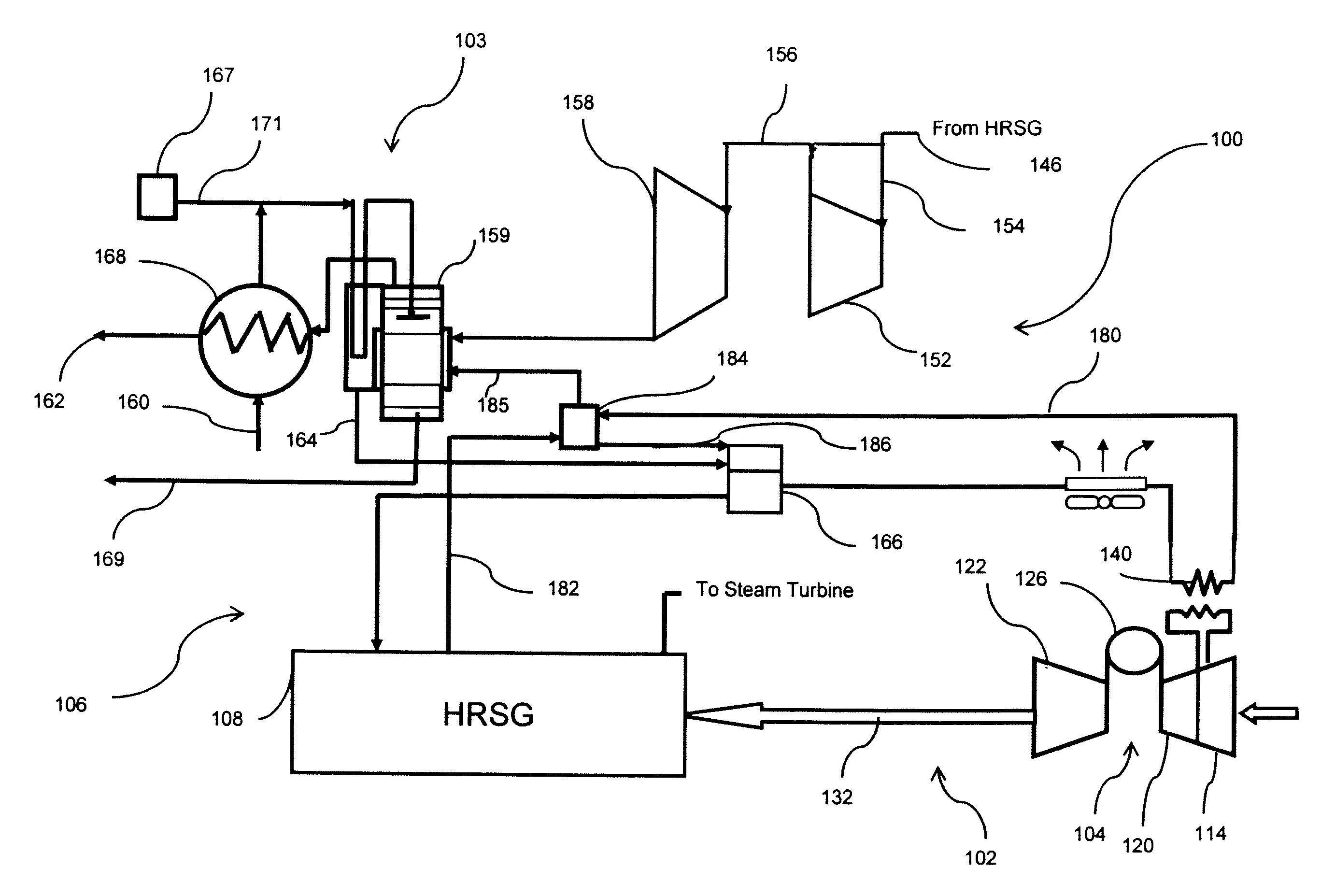
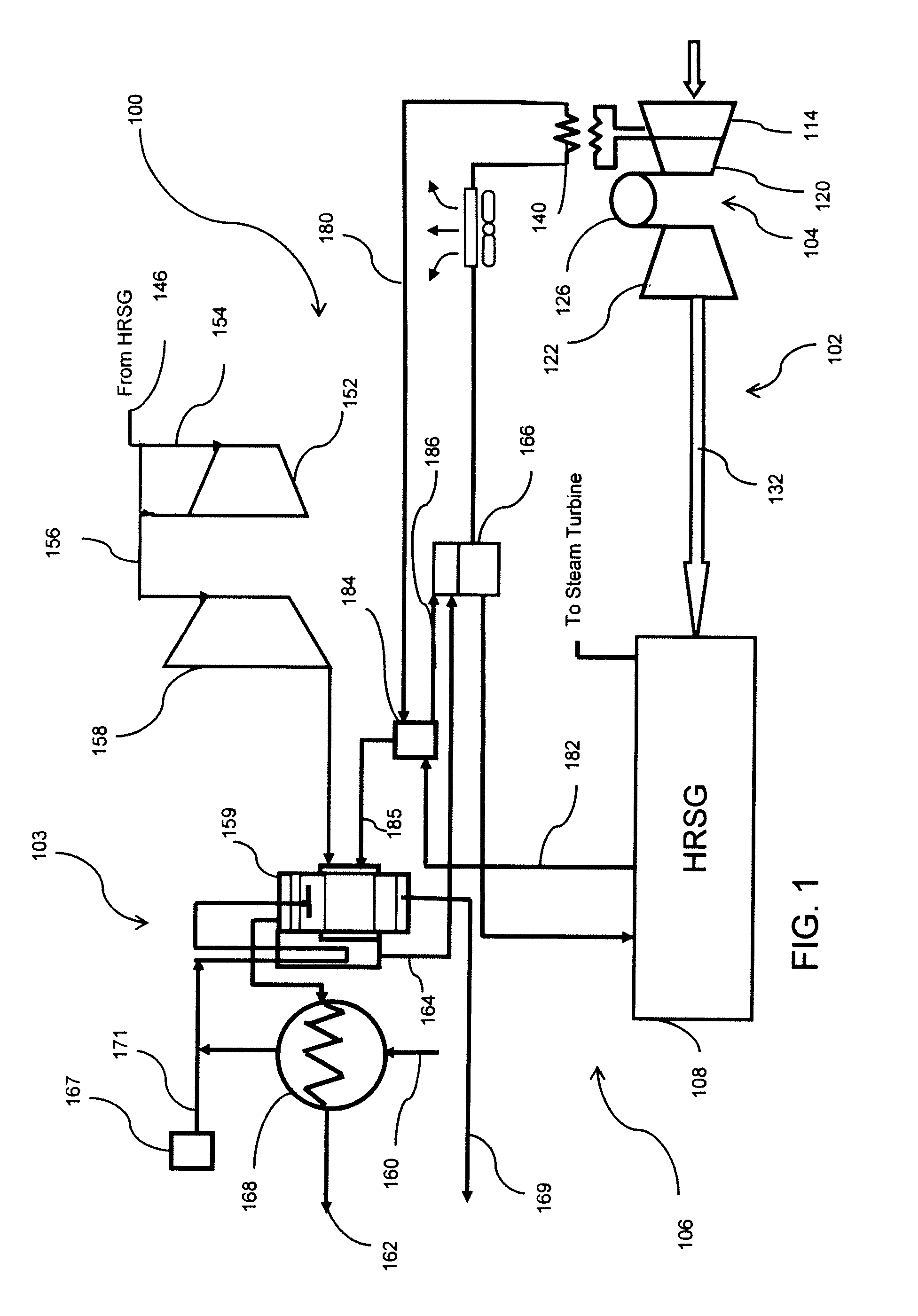
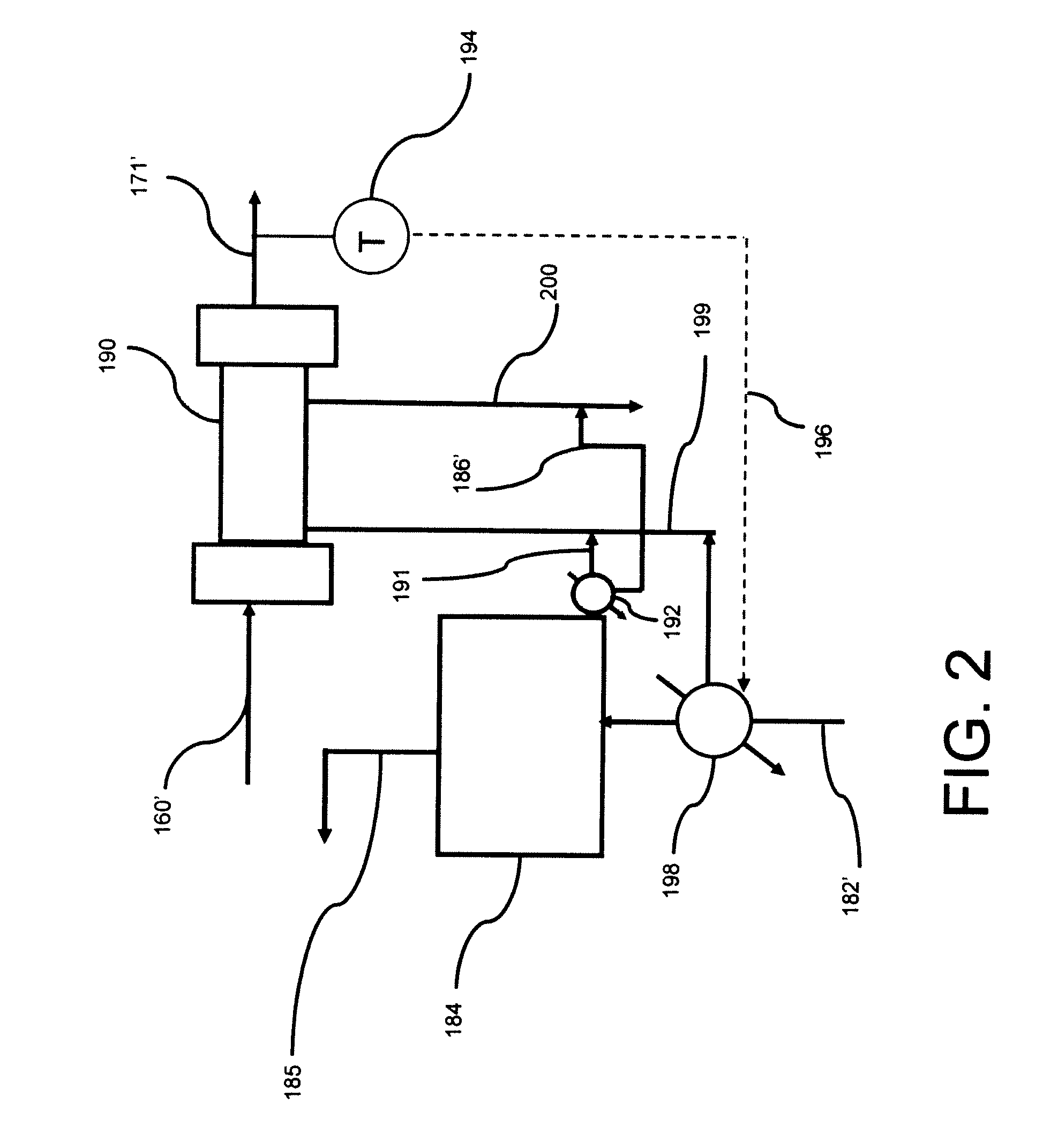
[0007]In one aspect, the invention is directed to a process for improving the efficiency of a combined-cycle power generation plant and thermal desalination unit. The process includes supplying exhaust gases from a gas turbine set used to generate electrical power to a heat recovery steam generator (HRSG) and then directing the steam from the HRSG to a steam turbine set. Salinous water is supplied into a thermal desalination unit, whose processes could be single or multi-effect distillation, multi-stage flash, membrane distillation, or forward osmosis. The illustrated embodiment considers a thermal desalination process with single-effect distillation. Steam exhausted from the steam turbine set is utilized in an effect of the desalination unit to produce a distillate vapor and brine from the effect by heat exchange. Additionally, steam is introduced steam from at least one additional heat source from the combined-cycle power generation plant to the effect to increase the mass flow rate of steam into the effect. In one embodiment, the additional heat source is an intercooler heat exchanger. Heated water from the intercooler heat exchanger is provided to a reduced atmosphere flash tank, and the steam flashed in the flash tank is provided to the effect. In another embodiment, the additional heat source is an economizer heat exchanger in the HSRG. Heated water from the economizer heat exchanger is provided to a reduced atmosphere flash tank, and the steam flashed in the flash tank is provided to the effect.
[0008]Another aspect of the invention is directed to a combined-cycle power generation plant and desalination unit. The plant includes a gas turbine set having a compressor and a gas turbine with a combustor therebetween. The compressor has a high pressure compressor and a low pressure compressor, wherein an intercooler heat exchanger is positioned between the high pressure compressor and the low pressure compressor. The plant also includes a steam turbine set and a HRSG which is connected to and which receives hot exhaust gas from the gas turbine set. The HRSG provides steam to the steam turbine set. The desalinization unit for distilling salinous water has at least one effect that receives exhaust steam from the steam turbine set. The plant also includes a reduced atmosphere flash tank configured to receive heated water from the intercooler heat exchanger. A portion of the heated water from the intercooler heat exchanger is flashed to steam in the flash tank and is then provided to the effect of the desalinization unit to increase the mass flow rate of steam into the effect. In another embodiment, the plant also contains an economizer heat exchanger in the HSRG. Heated water from the economizer heat exchanger is provided to the reduced atmosphere flash tank. A portion of the heated water from the economizer heat exchanger is flashed to steam in the flash tank and is then provided to the effect of the desalinization unit to increase the mass flow rate of steam into the effect.

Problems solved by technology

However, typical desalination plants in commercial application reduce electricity production from combined cycle power plants because they still extract relatively high-pressure steam that would otherwise be further expanded in the steam turbine.
Additionally, they do not effectively utilize other waste heat sources in the distillation process.

Method used


Image

  • Waste heat driven desalination process
  • Waste heat driven desalination process
  • Waste heat driven desalination process

Examples


Embodiment Construction

[0013]The invention will now be described in the following detailed description with reference to the drawings, wherein preferred embodiments are described in detail to enable practice of the invention. Although the invention is described with reference to these specific preferred embodiments, it will be understood that the invention is not limited to these preferred embodiments. But to the contrary, the invention includes numerous alternatives, modifications and equivalents as will become apparent from consideration of the following detailed description.

[0014]Approximating language, as used herein throughout the specification and claims, may be applied to modify any quantitative representation that could permissibly vary without resulting in a change in the basic function to which it is related. Accordingly, a value modified by a term or terms, such as “about”, is not limited to the precise value specified. In at least some instances, the approximating language may correspond to th...


PUM


Abstract

Disclosed is a process for improving the efficiency of a combined-cycle power generation plant and desalination unit. The process includes supplying exhaust gases from a gas turbine set used to generate electrical power to a heat recovery steam generator (HRSG) and then directing the steam from the HRSG to a steam turbine set. Salinous water is supplied into an effect of the desalination unit. Steam exhausted from the steam turbine set is utilized in the effect of the desalination unit to produce a distillate vapor and brine from the effect by heat exchange. Additionally, steam is introduced steam from at least one additional heat source from the combined-cycle power generation plant to the effect to increase the mass flow rate of steam into the effect. In one embodiment, the additional heat source is an intercooler heat exchanger. Heated water from the intercooler heat exchanger is provided to a reduced atmosphere flash tank, and the steam flashed in the flash tank is provided to the effect.

Description

BACKGROUND OF THE INVENTION[0001]1. Field of the Invention[0002]This invention relates generally to power generation and simultaneous desalinization of salinous water, and more specifically, to improving thermal efficiency by using other waste heat sources in addition the exhaust steam to heat water used in the desalination of salinous water.[0003]2. Description of Related Art[0004]Power generation using steam expansion is a common process. Condensate is fed to a boiler and heated. Steam is removed from the boiler and typically superheated. It then expands across a turbine, thereby doing work. The steam is then condensed and recycled to the boiler. A moderate amount of liquid is intermittently withdrawn from the boiler to prevent sludge accumulation. Treated fresh water is added to the system to compensate for material losses. Dual purpose desalination / power plants currently in use produce fresh water by using the exhaust steam as a source of heat for a distillation unit. Essentiall...

Claims


Application Information

Patent Timeline
IPC IPC(8): C02F1/06B01D3/06
CPCC02F1/04C02F1/041C02F1/06Y02E20/16C02F1/441C02F2103/08C02F1/16Y02W10/37Y02A20/131Y02A20/124
Inventor SHAPIRO, ANDREW PHILIPVORA, NISHITHTANG, CHING-JENHARDY, ALICIA JILLIAN JACKSONWESTERKAMP, DOUGLAS
Owner BL TECH INC
Learn More