Current sensing devices and methods

a current sensing and current technology, applied in the field of circuit elements, can solve the problems of laborious and expensive prior art attempts at manufacturing rogowski coils, and the output of a rogowski coil is typically highly linear, and achieve the effects of low cost, high manufacturing cost, and high outpu

Active Publication Date: 2011-06-23
PULSE ELECTRONICS
View PDF70 Cites 83 Cited by
  • Summary
  • Abstract
  • Description
  • Claims
  • Application Information

AI Technical Summary

Benefits of technology

[0016]In a sixth aspect of the invention, a scalable inductive device is disclosed. In one embodiment, the device comprises a number of winding segments, and the number of winding segments (and / or number of turns per segment) can be varied as desired so as to achieve a desired tradeoff between higher performance and higher cost of manufacturing.
[0017]In a seventh aspect of the invention, a low cost and highly precise inductive device is disclosed. In one embodiment, a number of segments are used to effectively approximate a circular, continuous Rogowski coil device.
[0018]In an eighth aspect of the invention, a user-tunable multi-coil assembly is disclosed. In one embodiment, two or more segmented coils are stacked (i.e., in juxtaposed disposition with a common central axis), such that the angular disposition (rotation) of the coils around the common axis can be varied by an installer or end user, and / or the number of coils present can be changed. As the segments of one coil are placed in different position with respect to the segments of the other coil(s) (and / or the number of coils increased or decreased), the output of the devices will vary, thereby allowing the installer / user to “tune” the effective output of the coil assembly to the desired level of performance.

Problems solved by technology

Furthermore, the output of a Rogowski coil is typically highly linear, even when subjected to large currents such as those used in electric power transmission, welding, or other pulsed power applications.
However, due to the relatively complex winding configurations involved, prior art attempts at manufacturing Rogowski type coils have been labor intensive and expensive.

Method used


Image

  • Current sensing devices and methods
  • Current sensing devices and methods
  • Current sensing devices and methods

Examples


Embodiment Construction

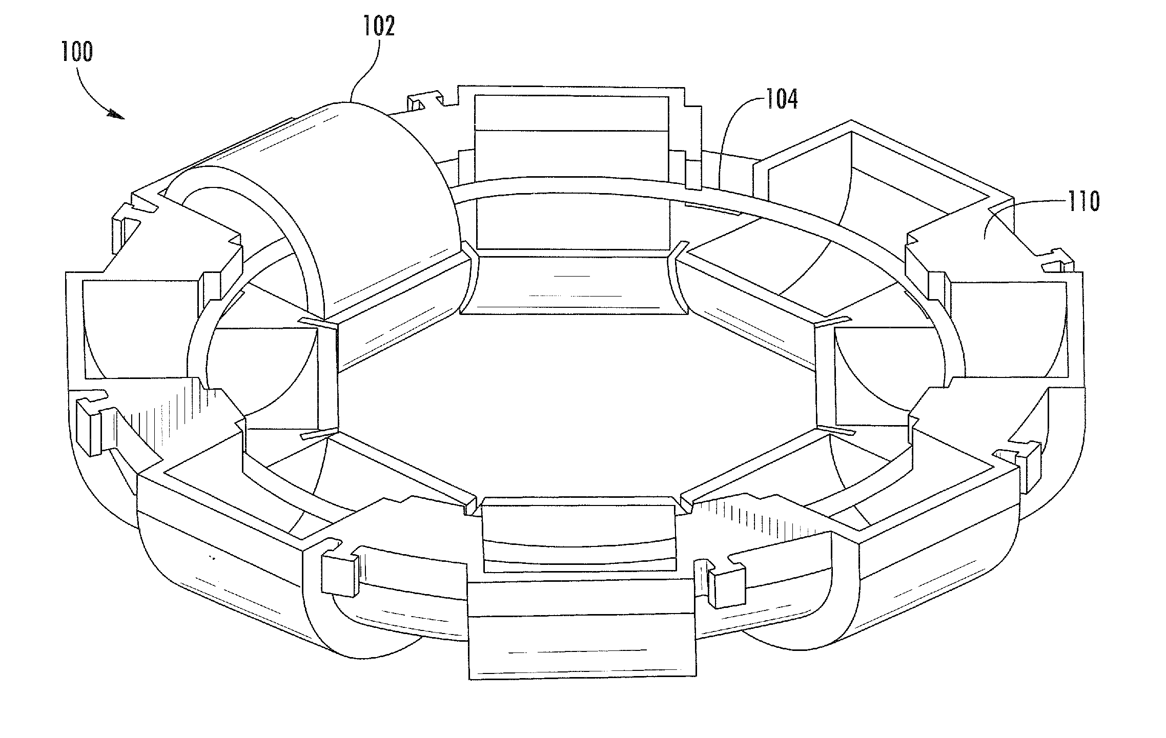
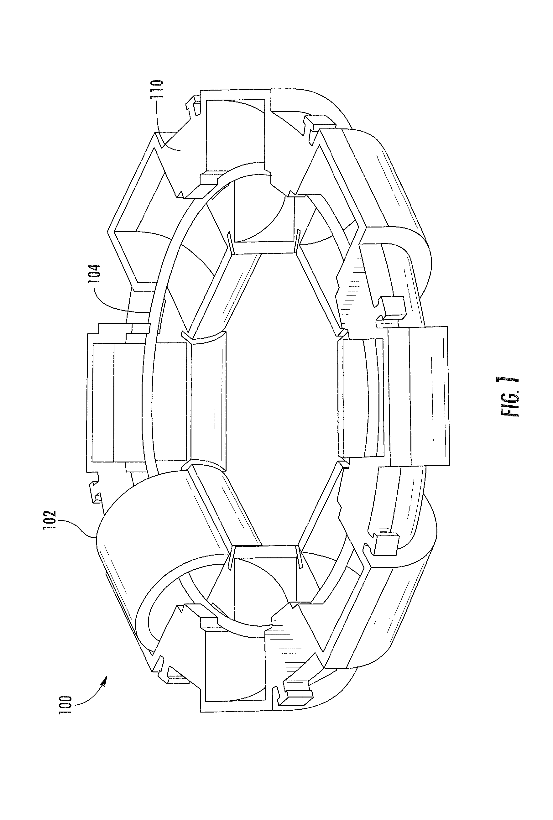
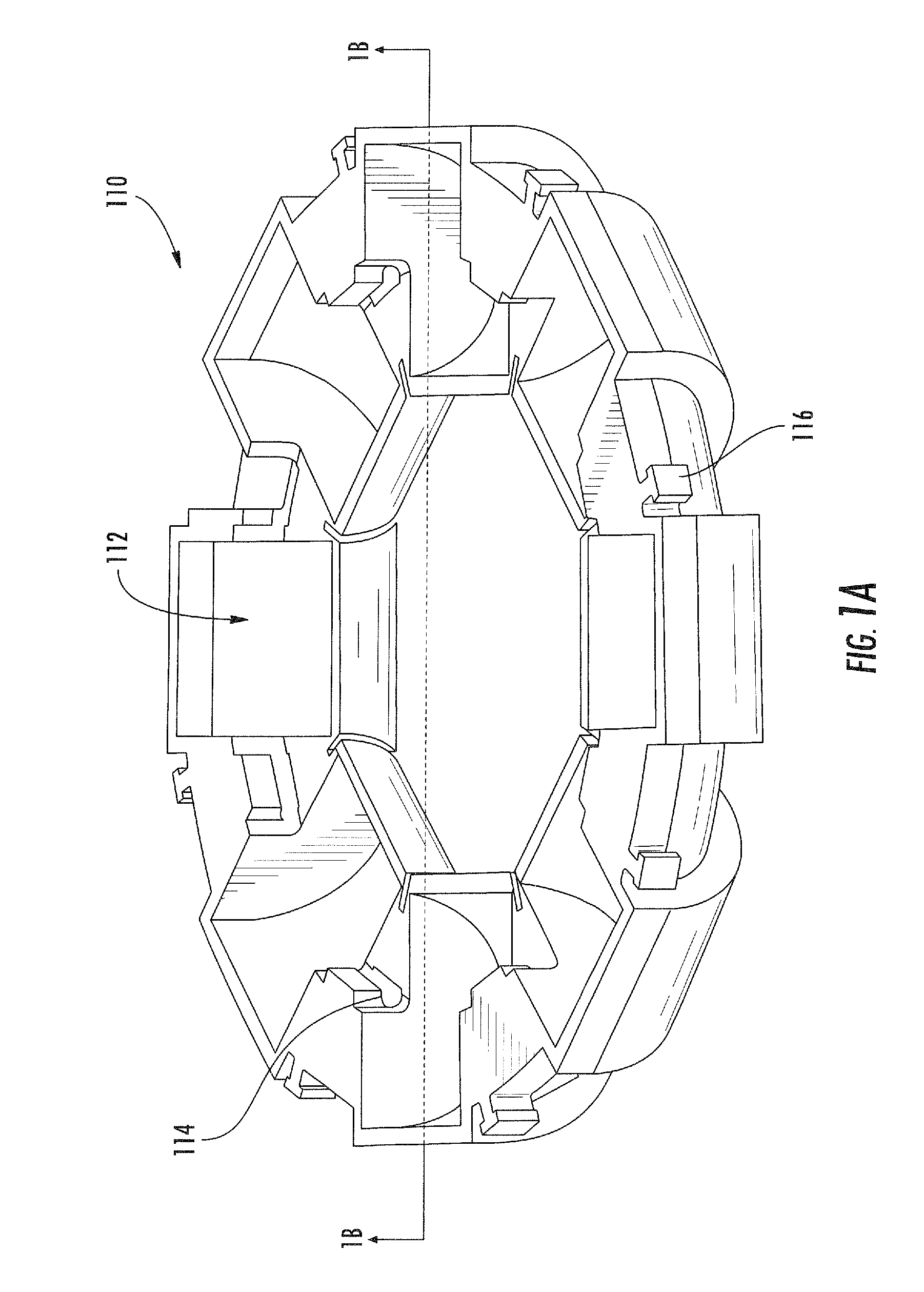
[0138]Reference is now made to the drawings wherein like numerals refer to like parts throughout.

[0139]As used herein, the terms “bobbin” and “form” (or “former”) are used without limitation to refer to any structure or component(s) disposed on or within or as part of an inductive device which helps form or maintain one or more windings of the device.

[0140]As used herein, the terms “electrical component” and “electronic component” are used interchangeably and refer to components adapted to provide some electrical and / or signal conditioning function, including without limitation inductive reactors (“choke coils”), transformers, filters, transistors, gapped core torpids, inductors (coupled or otherwise), capacitors, resistors, operational amplifiers, and diodes, whether discrete components or integrated circuits, whether alone or in combination.

[0141]As used herein, the term “inductive device” refers to any device using or implementing induction including, without limitation, inductor...


PUM

PropertyMeasurementUnit
diameteraaaaaaaaaa
conductiveaaaaaaaaaa
electromagnetic noiseaaaaaaaaaa

Abstract

A low-cost and high-precision current sensing device and methods for use and manufacturing. In one embodiment, the current sensing apparatus comprises a Rogowski-type coil which is manufactured in segments so as to facilitate the manufacturing process. In an exemplary embodiment, the current sensing apparatus segments comprise a number of bobbin elements that are wound and subsequently formed into complex geometric shapes such as torus-like shapes. In an alternative embodiment, bonded windings are utilized which allow the segments to be formed without a bobbin or former. In yet another alternative embodiment, the aforementioned current sensing devices are stacked in groups of two or more. Methods of manufacturing and using the aforementioned current sensing apparatus are also disclosed.

Description

PRIORITY[0001]This application is a continuation-in-part of and claims priority to U.S. patent application Ser. No. 12 / 684,056 filed Jan. 7, 2010 of the same title, which is a continuation-in-part of and claims priority to U.S. patent application Ser. No. 12 / 567,622 filed Sep. 25, 2009 of the same title, which claims priority to U.S. Provisional Patent Application Ser. No. 61 / 230,474 filed Jul. 31, 2009 of the same title, each of which is incorporated herein by reference in its entirety.COPYRIGHT[0002]A portion of the disclosure of this patent document contains material that is subject to copyright protection. The copyright owner has no objection to the facsimile reproduction by anyone of the patent document or the patent disclosure, as it appears in the Patent and Trademark Office patent files or records, but otherwise reserves all copyright rights whatsoever.1. FIELD OF THE INVENTION[0003]The present invention relates generally to circuit elements and more particularly in one exem...

Claims


Application Information

Patent Timeline
Patent Type & Authority Applications(United States)
IPC IPC(8): H01F27/29H01F7/06
CPCY10T29/49071G01R15/181G01R19/0092
Inventor LINT, JAMES DOUGLASJIN, FUXUEMICHEL, FRANCISCOALDACO, VICTOR
Owner PULSE ELECTRONICS
Why Eureka
Try Eureka