Color filter using surface plasmon, liquid crystal display device and method for fabricating the same

a surface plasmon and color filter technology, applied in the field of color filters, can solve the problems of difficult to have a transmittance rate more than 30%, complicated process of general color filter fabrication, and increased power consumption of backlight, so as to enhance the aperture ratio and the transmittance rate of the lc panel

Inactive Publication Date: 2011-06-23
LG DISPLAY CO LTD
View PDF25 Cites 23 Cited by
  • Summary
  • Abstract
  • Description
  • Claims
  • Application Information

AI Technical Summary

Benefits of technology

[0021]Therefore, one object of the present invention is to provide a color filter using a surface plasmon, a liquid crystal display (LCD) device and a method for fabric

Problems solved by technology

Accordingly, it is difficult to have a transmittance rate more than 30%.
Due to this low transmittance rate of the LC panel, power consumption by a backlight is increased.
The general color filter is fabric

Method used


Image

  • Color filter using surface plasmon, liquid crystal display device and method for fabricating the same
  • Color filter using surface plasmon, liquid crystal display device and method for fabricating the same
  • Color filter using surface plasmon, liquid crystal display device and method for fabricating the same

Examples


first embodiment

[0073]In the color filter using a surface plasmon according to the present invention, a bandwidth and a position of a prime peak wavelength of transmitted light are greatly influenced by a viewing angle.

[0074]FIG. 4 is a graph showing changes of a prime peak wavelength of transmitted light according to an incident angle, which shows a transmission intensity of transmitted light measured when an incident angle (θ) is changed to 0°˜24° (T. Ebbesen, et al, Nature, 667, 1998).

[0075]As shown in FIG. 4, a bandwidth and a position of a prime peak wavelength of transmitted light are greatly influenced by a viewing angle. The prime peak wavelength of transmitted light by a surface plasmon resonance has a change rate of 8.3 nm / ° degree.

[0076]It can be seen that light perpendicularly incident onto the color filter has a maximized transmission rate, and the transmission rate is significantly decreased when the incidence angle (θ) is increased.

[0077]This may cause a problem that a color of a des...

second embodiment

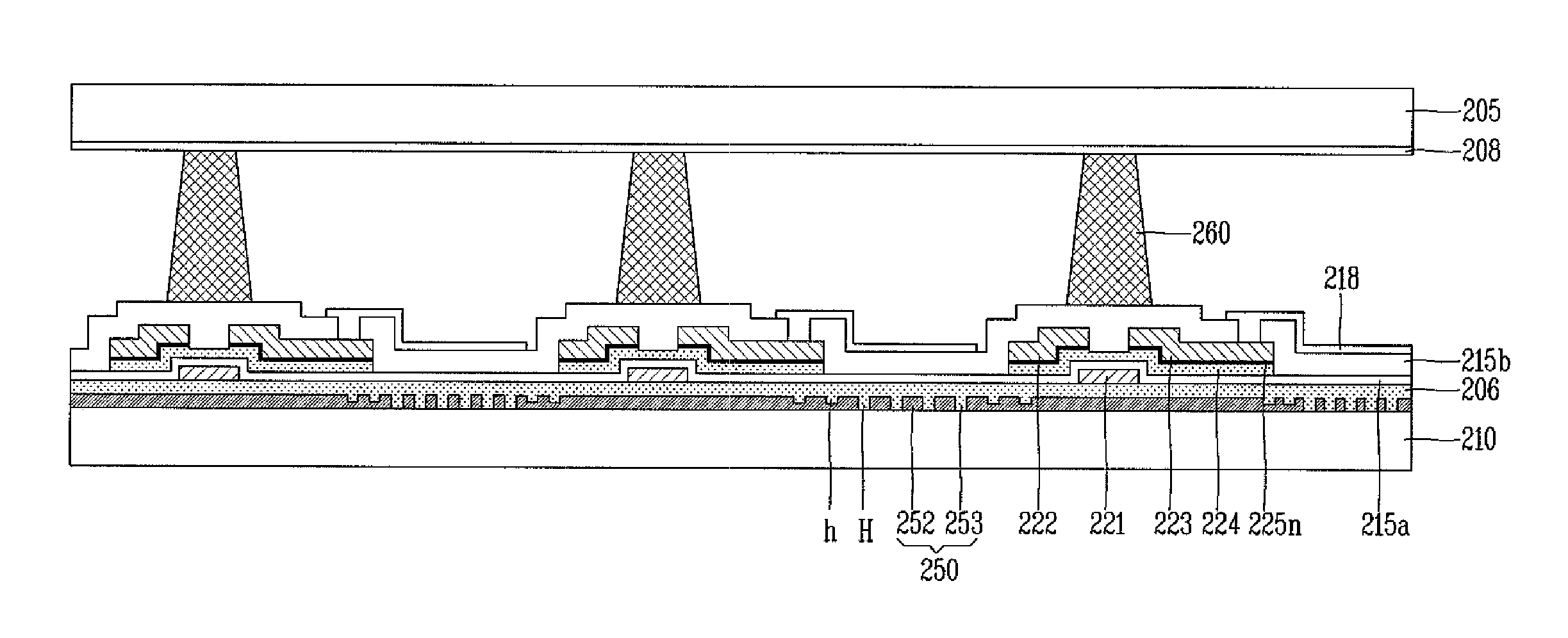
[0080]An object of the present invention is to fabricate a color filter using a surface plasmon emitted from a surface in the form of beam with an enhanced transmittance rate, and enhanced collimation and directivity.

[0081]More concretely, the color filter using a surface plasmon according to the second embodiment of the present invention has a plurality of grooves having a period and formed at a region encompassing the plurality of holes of the transmissive pattern. This may implement beam having a very narrow divergence angle of about ±3°. This may reduce dependency of a prime peak wavelength of transmitted light on a viewing angle, and enhance a transmittance rate and collimation.

[0082]In the second embodiment of the present invention, a prime peak wavelength of transmitted light is not influenced by changes of a viewing angle or a measuring angle. Furthermore, since light divergence to an interface between sub-pixels is prevented, loss of transmitted light may be reduced. Beside...


PUM


Abstract

Discussed are a color filter using a surface plasmon, a liquid crystal display (LCD) device and a method for fabricating the same, capable of enhancing a transmittance rate of an LC panel, by forming a transmissive pattern having a plurality of sub-wavelength holes having a period at a metal layer so that light of a specific wavelength can be selectively transmitted, and capable of simplifying the entire processed.

Description

CROSS-REFERENCE TO RELATED APPLICATION[0001]Pursuant to 35 U.S.C. §119(a), this application claims the benefit of earlier filing date and right of priority to Korean Application 10-2009-0127433, filed on Dec. 18, 2009, the content of which is incorporated by reference herein in its entirety.BACKGROUND OF THE INVENTION[0002]1. Field of the Invention[0003]The present invention relates to a color filter using a surface plasmon, a liquid crystal display (LCD) device and a method for fabricating the same, and more particularly, to a color filter using a surface plasmon and having a three-dimensional (3D) pattern structure provided with a transmissive pattern for selectively transmitting light of a specific wavelength, an LCD device and a method for fabricating the same.[0004]2. Discussion of the Related Art[0005]As concerns about an information displays and demands for portable information media are increased, research and commercialization of flat panel displays (FPD) replacing the gene...

Claims


Application Information

Patent Timeline
IPC IPC(8): G02F1/1335H01L33/34
CPCG02B5/008G02B5/201G02F1/133514G02F2203/34G02F2201/121G02F2203/055G02F2203/10G02F1/1343G02B5/20G02F1/1335
Inventor YOON, MIN-SUNG
Owner LG DISPLAY CO LTD
Why Eureka
Try Eureka