Capacitor Module, Power Converter, Vehicle-Mounted Electrical-Mechanical System

a technology of capacitors and modules, applied in the direction of fixed capacitors, electric devices, engine-driven generators, etc., can solve the problems of inability to realize a sufficient reduction of inductance, inability to achieve cooling based on convection of air within the space, and large weight of the capacitor module. , to achieve the effect of reducing surge voltage, low inductance and small siz

Active Publication Date: 2011-06-23
HITACHI ASTEMO LTD
View PDF10 Cites 18 Cited by
  • Summary
  • Abstract
  • Description
  • Claims
  • Application Information

AI Technical Summary

Benefits of technology

[0013]An object of the present invention is to provide a space-saving capacitor module which has not only a connecting structure ensuring a low inductance and moderation of stresses, but also a structure suitable for cooling.
[0014]To achieve the above object, the capacitor module of the present invention is featured in reducing parasitic inductance of connecting portions. The capacitor module comprises a plurality of capacitors; and a laminate electrically connected to the plurality of capacitors and made up of a first wide conductor and a second wide conductor joined in a layered form with an insulation sheet interposed between the first and second wide conductors, the laminate comprising a first flat portion including the plurality of capacitors which are supported thereon and electrically connected thereto; a second flat portion being continuous with the first flat portion and extending at a large width in a direction away from the plurality of capacitors supported on the first flat portion; and connecting portions formed at ends of the first flat portion and the second flat portion and electrically connected to the exterior.
[0020]Thus, according to the present invention, the capacitor module can be obtained which has the connecting structure ensuring a low inductance and moderation of stresses and which is suitable for reducing a surge voltage caused at the time of switching in the power converter. The power converter having a small size and a high power density can also be obtained by using the capacitor module, and the vehicle-mounted electrical-mechanical system can further be obtained by using the power converter.

Problems solved by technology

However, a capacitor module constructed by combining a plurality of capacitors with each other is large and weight.
Accordingly, when the capacitors are connected in proximity relation as in the known techniques, stresses are concentrated in an electrically connecting portion, thus causing rupture in, e.g., an environment of severe temperature difference within an inverter for the HEV and an environment of severe vibration encountered when the HEV is driven over a road block or other level differences in roads.
Such a solution, however, increases inductance in the connecting portion and cannot realize a sufficient reduction of inductance.
In particular, an inverter for the HEV is usually installed in a closed space where the environmental temperature in use is 100° C. or higher and cooling based on convection of air within the space is not expected.
In addition, because the capacitors and the power semiconductor module are arranged side by side on a plane, the known techniques are not suitable for satisfying requirements demanded in the inverter for the HEV, i.e., space-saving installation, wiring with a low inductance, and a layered structure in which the capacitors are installed over the power semiconductor module.

Method used


Image

  • Capacitor Module, Power Converter, Vehicle-Mounted Electrical-Mechanical System
  • Capacitor Module, Power Converter, Vehicle-Mounted Electrical-Mechanical System
  • Capacitor Module, Power Converter, Vehicle-Mounted Electrical-Mechanical System

Examples


first embodiment

[0044]A capacitor module, a power converter, and a vehicle-mounted electrical-mechanical system according to the present invention will be described below with reference to FIGS. 1-12.

[0045]In the following embodiment, a vehicle-mounted power converter is described, by way of example, as the power converter in which is employed the capacitor module of the present invention.

[0046]The construction described below is also applicable to DC-DC power converters, such as a DC / DC converter and a DC chopper. Further, the construction described below is applicable to power converters used for industrial and domestic purposes.

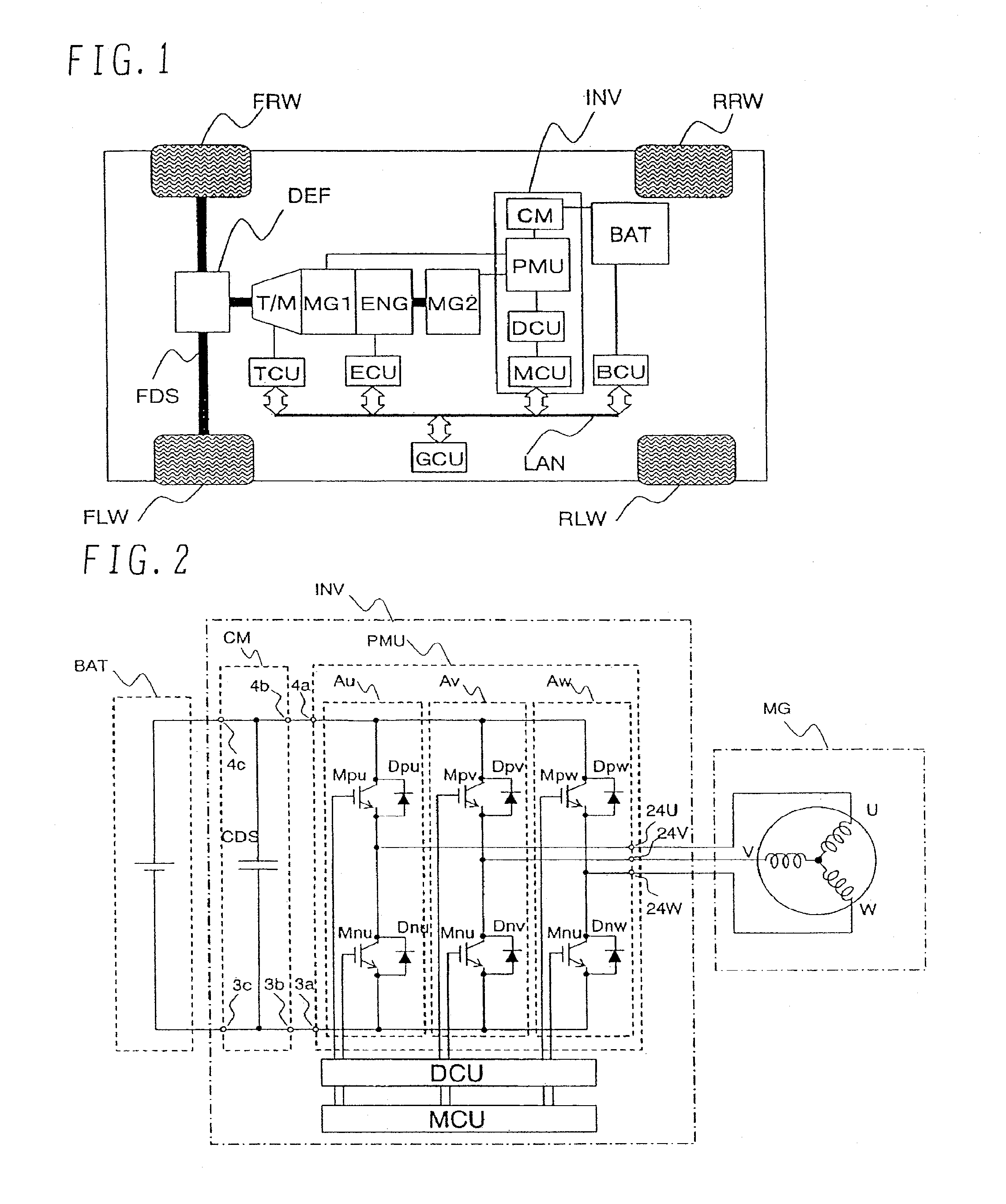
[0047]FIG. 1 is a block diagram of a hybrid electric vehicle (HEV) in which a vehicle-mounted electrical-mechanical system constructed of a power converter INV using the capacitor module according to the first embodiment of the present invention is combined with an internal combustion engine system.

[0048]The HEV to which is applied this first embodiment includes front whe...

second embodiment

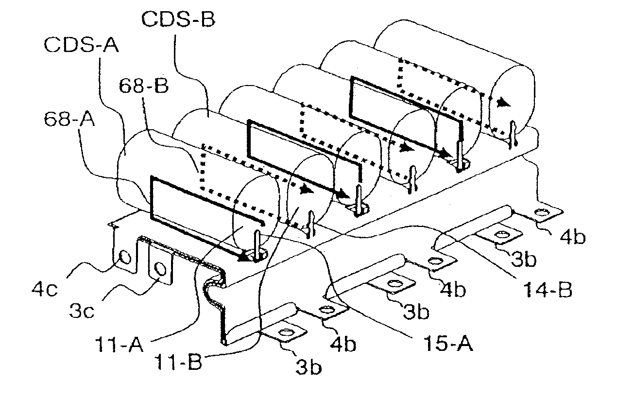
[0144]The construction of a capacitor module CM and a power converter INV according to the present invention will be described below with reference to FIGS. 13-20.

[0145]This second embodiment enables, in the motor system shown in FIG. 1, the power converter INV for controlling two motors MG1 and MG2 to be realized with a low inductance, a stress moderating structure and a smaller size.

[0146]FIG. 13 is a perspective view showing the construction of each capacitor module according to the second embodiment of the present invention. FIG. 14 is a plan view showing the arrangement of each power module according to the second embodiment of the present invention. FIGS. 17A and 17B are each a sectional view showing the power converter according to the second embodiment of the present invention. FIG. 18 is a circuit diagram showing the entire construction of the power converter INV according to the second embodiment of the present invention. Note that, in those drawings, the same characters a...

third embodiment

[0185]The construction of a capacitor module according to the present invention is shown in FIG. 21.

[0186]FIG. 21 is an exploded perspective view showing the construction of a capacitor module according to a third embodiment of the present invention. Note that, in FIG. 21, the same characters as those in FIG. 4 denote the same parts.

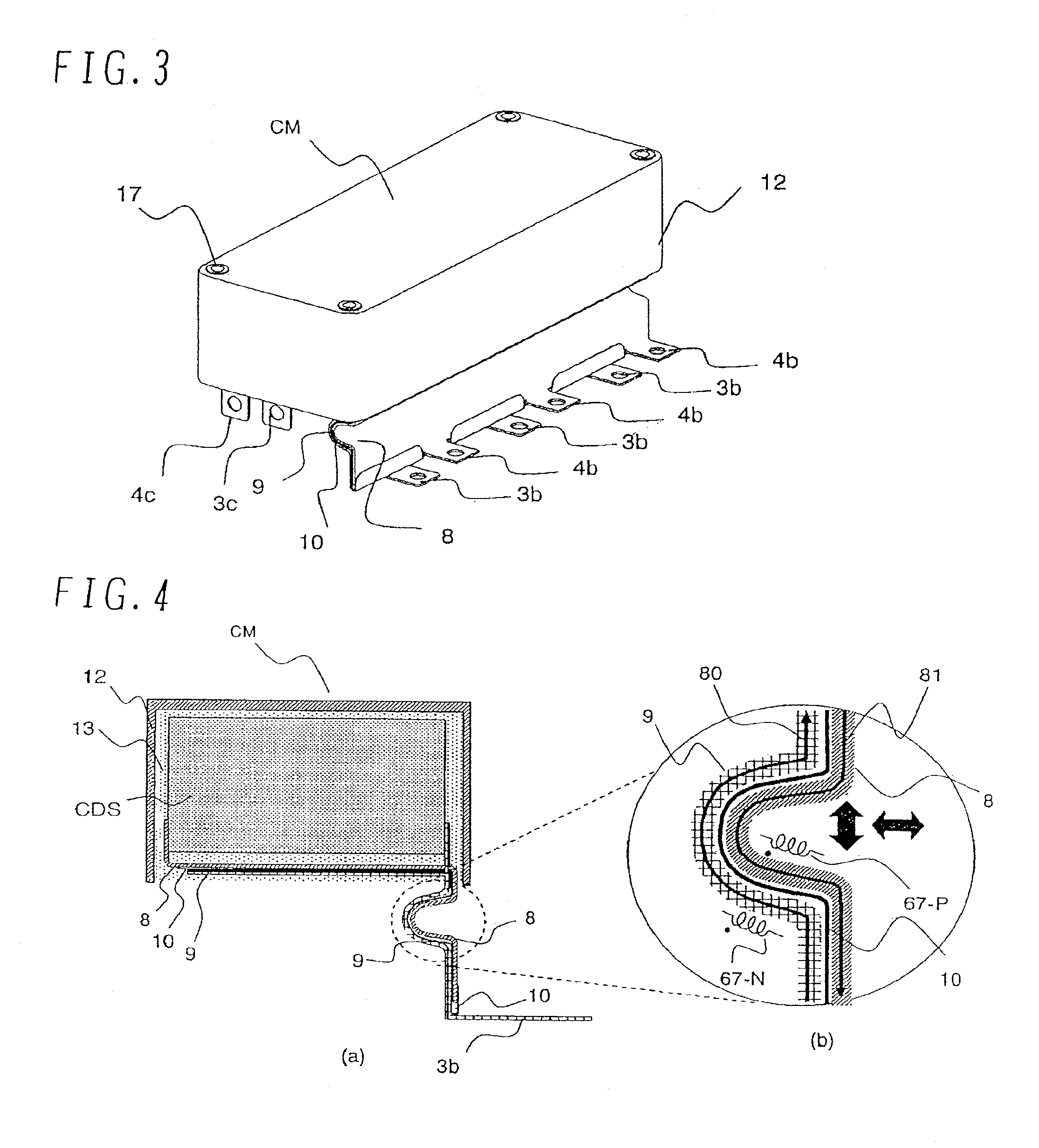
[0187]In this third embodiment, the basic construction of a capacitor module CM is the same as that of the capacitor module CM shown in FIGS. 4-10. However, the U-shaped bent structure, shown in FIG. 4, is not provided in the second flat portion of each of the layered wide conductors 8 and 9.

[0188]According to this third embodiment, although the effect of moderating stresses in the connecting portion is not so expected as the case including the bent structure, a certain effect of moderating stresses and reducing inductance can be realized because led-out portions of the wide conductors are in the layered form.


PUM


Abstract

A capacitor module in which the structure of a connecting portion is highly resistant against vibration and has a low inductance. The capacitor module includes a plurality of capacitors and a laminate made up of a first wide conductor and a second wide conductor joined in a layered form with an insulation sheet interposed between the first and second wide conductors. The laminate comprises a first flat portion including the plurality of capacitors which are supported thereon and electrically connected thereto, a second flat portion continuously extending from the first flat portion while being bent, and connecting portions formed at ends of the first flat portion and the second flat portion and electrically connected to the exterior.

Description

[0001]This application is a continuation of U.S. patent application Ser. No. 13 / 037,888, filed Mar. 1, 2011, which is a continuation of U.S. patent application Ser. No. 12 / 714,899, filed Mar. 1, 2010, which is a continuation of U.S. patent application Ser. No. 11 / 600,124, filed Nov. 16, 2006, which in turn claims the priority of Japanese application 2005-332897, filed Nov. 17, 2005. The entire disclosure of each of the above-identified applications is incorporated herein by reference.BACKGROUND OF THE INVENTION[0002]1. Field of the Invention[0003]The present invention relates to a capacitor module, a power converter, and a vehicle-mounted electrical-mechanical system.[0004]2. Description of the Related Art[0005]Recently, a power semiconductor device capable of switching a large current has been developed. A power converter using such a power semiconductor device is able to supply electric power to a load, e.g., a motor, with high efficiency through the switching. Therefore, the powe...

Claims


Application Information

Patent Timeline
Patent Type & Authority Applications(United States)
IPC IPC(8): H01G4/224
CPCB60K1/02B60L2200/26B60K6/48B60L11/005B60W10/06B60W10/08B60W20/00H01G2/04H01G4/228H01G4/38H01G9/008H01G9/08H01G9/14H01G9/26H02M7/003Y02T10/6221Y02T10/6286Y02T10/7022B60K6/28H01L2224/48091H01L2924/1305H01L2924/13055H01L2924/13091B60L3/003B60L15/007B60L2240/525B60L2270/145H01L2924/00011H01L2224/49111B60L50/40B60L50/61B60L50/16Y02T10/62Y02T10/64Y02T10/70Y02T10/7072Y02T10/92H05K7/14329H01L2924/00014H01L2924/00H01L2924/01033H02J7/34H02M3/07
Inventor AZUMA, KATSUNORIINABA, MASAMITSUMORI, MUTSUHIRONAKAJIMA, KENICHIRO
Owner HITACHI ASTEMO LTD
Why Eureka
Try Eureka