Radio communication apparatus and radio communication system

a radio communication system and radio communication technology, applied in the field of radio communication techniques, can solve the problems of difficult to allocate a wide range of bands continuously, insufficient uplink resources, etc., and achieve the effects of enhancing the effect of scheduling and amc, improving the transmission efficiency of the whole system, and efficient reporting of channel quality information on the communication band as a whol

Active Publication Date: 2011-06-23
GUANGDONG OPPO MOBILE TELECOMM CORP LTD
View PDF13 Cites 25 Cited by
  • Summary
  • Abstract
  • Description
  • Claims
  • Application Information

AI Technical Summary

Benefits of technology

[0030]According to the present invention, the receiver can continue to report CQIs with frequencies suitable for the variations of the channels of both bands. Thus, the channel quality information on the communication band as a whole can be reported efficiently. As a result, in communication performed while reporting the CQIs associated with all the bands, the effects of the scheduling and AMC are enhanced, whereby the transmission efficiency of the whole system is improved.
[0031]The description herein includes the contents of the description and / or the drawings provided in Japanese Patent Application Publication No. 2008-227164, which is the basis of priority of the present application.

Problems solved by technology

However, when all terminals return information on the subcarriers to a base station, the uplink resource often becomes insufficient.
However, there may be a band already being used by an existing vendor, and hence it is difficult to allocate a wide range of bands continuously.

Method used


Image

  • Radio communication apparatus and radio communication system
  • Radio communication apparatus and radio communication system
  • Radio communication apparatus and radio communication system

Examples


first embodiment

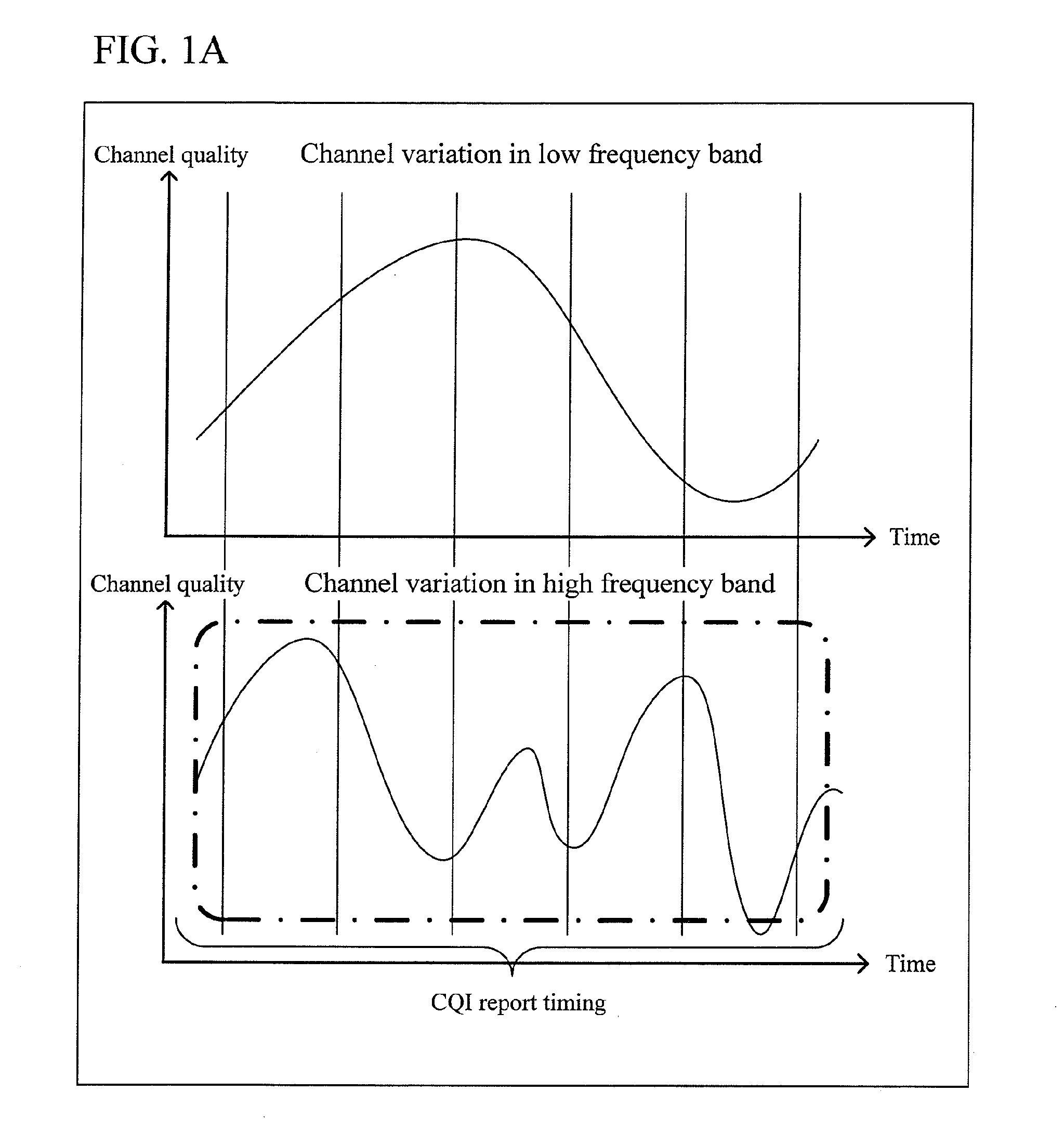
[0054]A radio communication apparatus according to the present invention will be described below. By referring to FIGS. 1A and 1B, differences caused by channel variations will be described.

[0055]While the receiver is moving relative to the transmitter, channel variation occurs due to the influence of the Doppler effect and the like related to that movement. The rate of the channel variation (i.e., Doppler frequency) is proportional to the moving speed of the receiver and the frequency of the channel. For this reason, even with the same receiver, the channel variation rate is higher in a lower frequency band than a higher frequency band.

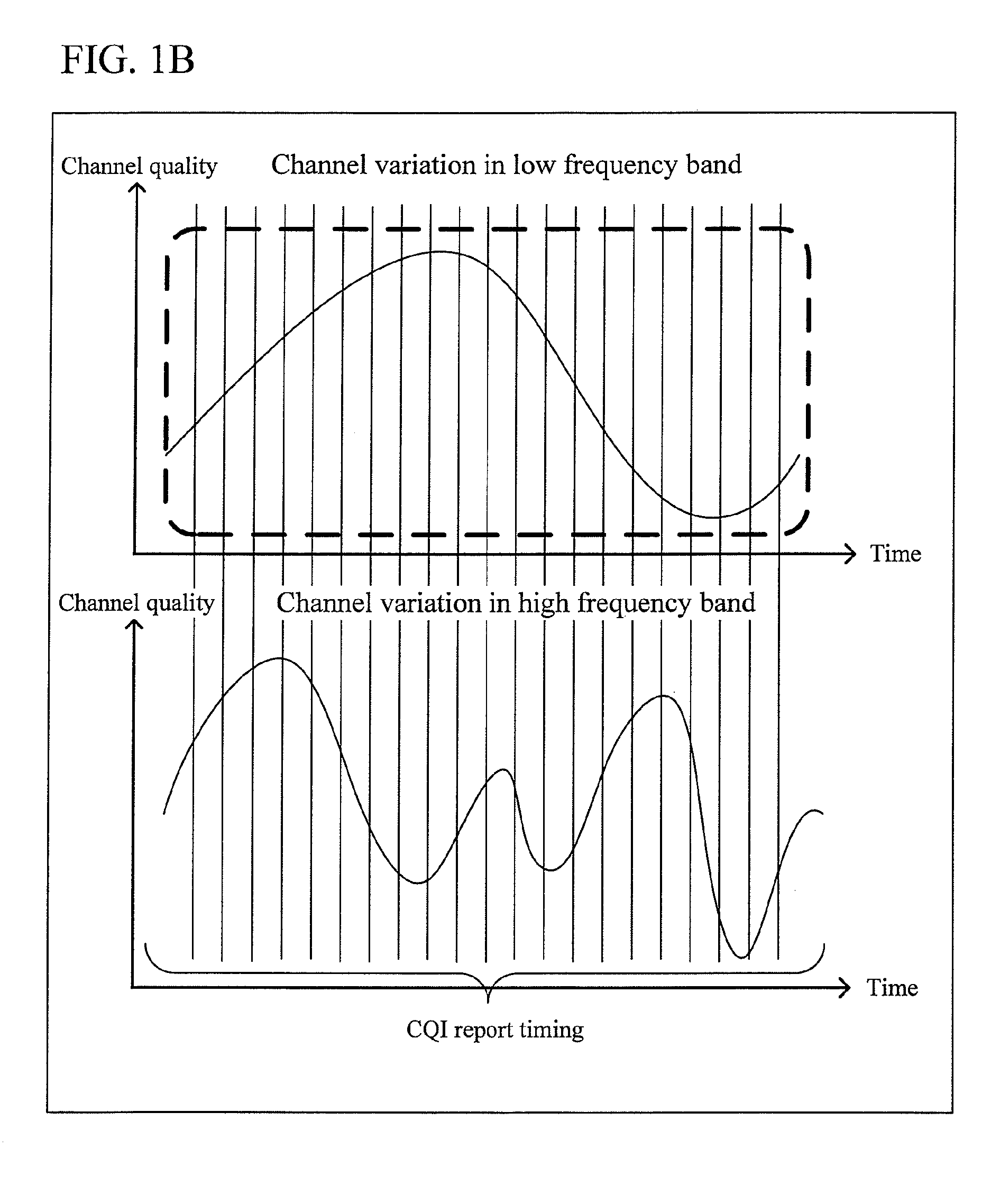
[0056]FIG. 1A is a diagram showing an example of channel variation in a case where communication is performed using two different bands. FIG. 1A shows an example where, as the upper diagram shows, the CQIs of all the bands are transmitted at an interval suitable for a low frequency band. In FIG. 1A, each solid line extending vertically indicates a ti...

second embodiment

[0108]Next, the present invention will be described.

[0109]A radio communication technique according to the embodiment of the present invention relates to a case where CQIs based on respective bands are transmitted periodically in a communication system where data is transmitted and received in units of frame having a fixed time length.

[0110]Since other configurations of the transmitter and the receiver are similar to those in the first embodiment (FIGS. 2 and 3), description thereof is omitted. In the following, the CQI transmission timing, which is a characteristic feature of the embodiment, will be described in detail.

[0111]The embodiment is an embodiment based on a case where the frame length is fixed for both uplink and downlink. Description will be given of the relationship between a transmitted frame and a received frame for AMC and scheduling, which serves as the premise of the embodiment. FIG. 8 is a diagram showing the relationship between a receiver and a transmitter in a ...

third embodiment

[0127]FIG. 11 is a sequence diagram showing CQI transmission timings in the present invention. In FIG. 11, the CQI is returned every frame regardless whether the band is of a high or low frequency (the CQI may not be returned every frame as long as returned once in every two frames, for example). At this time, the CQI associated with a low frequency band is returned R times in every N times, whereas the CQI associated with a high frequency band is returned N−R times in every N times. Here, R is set as a number smaller than N−R. To be specific, while returning the CQI N times, the receiver returns the CQI based on the low frequency band R times and returns the CQI based on the high frequency band N−R times (where R

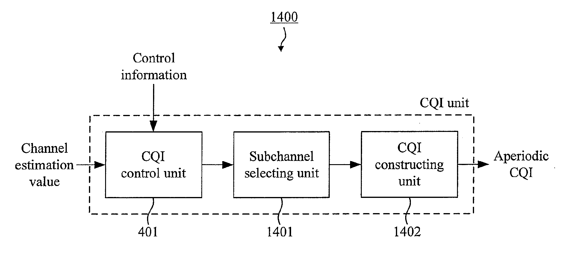
[0128]With the control information generating unit 351, the CQI control infor...


PUM


Abstract

A CQI control unit 401 inputs, to a subchannel selecting unit 402, subchannel estimation values for report bands which are based on control information received from a control information separating unit 221, at report timings based on the control information. The subchannel selecting unit 402 selects a predetermined number (M) of subchannels on the basis of the received subchannel estimation values, and inputs information indicating the selected subchannels and the qualities of the selected channels to a CQI constructing unit 403. Based on a predetermined format, the CQI constructing unit 403 constructs CQIs by using the qualities of the selected channels and the information indicating the selected channels, and inputs the CQIs to the coding unit 210. Here, as the channel quality, an average value of each of SNR, SINR, and CINR of subcarriers belonging to the subchannel is used. Alternatively, the poorest quality among the subcarriers included in the subchannel may be used as the channel quality of the subchannel, or information indicating the MCS required by the receiver may be used as the channel quality. In this way, it is possible to provide a method that enables the transmission of CQIs at their optimum intervals even in a case of a system using multiple discontinuous bands.

Description

TECHNICAL FIELD[0001]The present invention relates to a radio communication technique, and particularly to a technique for suppressing deterioration of the transmission characteristics caused by the reporting of CQIs.BACKGROUND ARTAbout AMC[0002]As a third generation communication method, there is high speed down link packet access (HSDPA) which is developed by the 3GPP. In HSDPA, adaptive modulation and coding (AMC) is used to achieve high-quality, high-speed transmission (for example, see Non-patent Literature 1). In HSDPA, based on report information, i.e., CQI (Channel Quality Indicator), which a base station receives from a terminal, an MCS (Modulation and Coding Scheme), i.e., the modulation scheme and the coding ratio, is controlled adaptively. As the channel quality, e.g., SNR (Signal to Noise power Ratio) or SINR (Signal to Interference plus Noise power Ratio) is used.About OFDM[0003]Meanwhile, as a prospective next generation communication method, there is OFDM (Orthogonal...

Claims


Application Information

Patent Timeline
Patent Type & Authority Applications(United States)
IPC IPC(8): H04W24/10H04W72/04
CPCH04W8/24H04W72/04H04W72/02H04W24/10
Inventor NAKANO, HIROSHIONODERA, TAKESHINOGAMI, TOSHIZO
Owner GUANGDONG OPPO MOBILE TELECOMM CORP LTD
Why Eureka
Try Eureka