Apparatus and method for data transmission in sc-fdma system with multiple antennas

a data transmission and antenna technology, applied in the field of wireless communications, can solve the problems of path loss, limited bandwidth, wireless channel experience, etc., and achieve the effect of reducing the peak-to-average power ratio (papr)

a data transmission and antenna technology, applied in the field of wireless communications, can solve the problems of path loss, limited bandwidth, wireless channel experience, etc., and achieve the effect of reducing the peak-to-average power ratio (papr)

US20110149944A1Active Publication Date: 2011-06-23LG ELECTRONICS INC

Image

  • Apparatus and method for data transmission in sc-fdma system with multiple antennas
  • Apparatus and method for data transmission in sc-fdma system with multiple antennas
  • Apparatus and method for data transmission in sc-fdma system with multiple antennas

Examples


Embodiment Construction

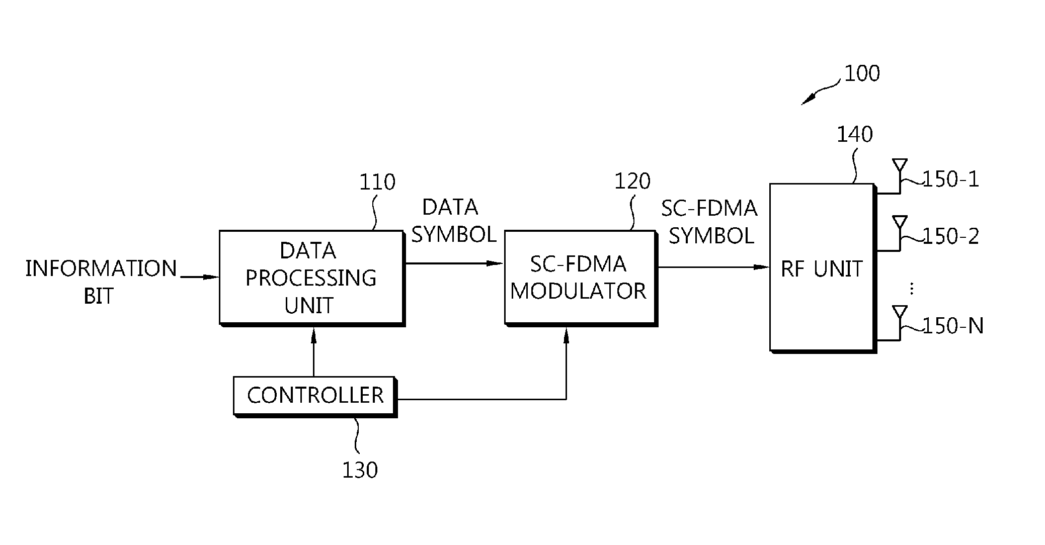
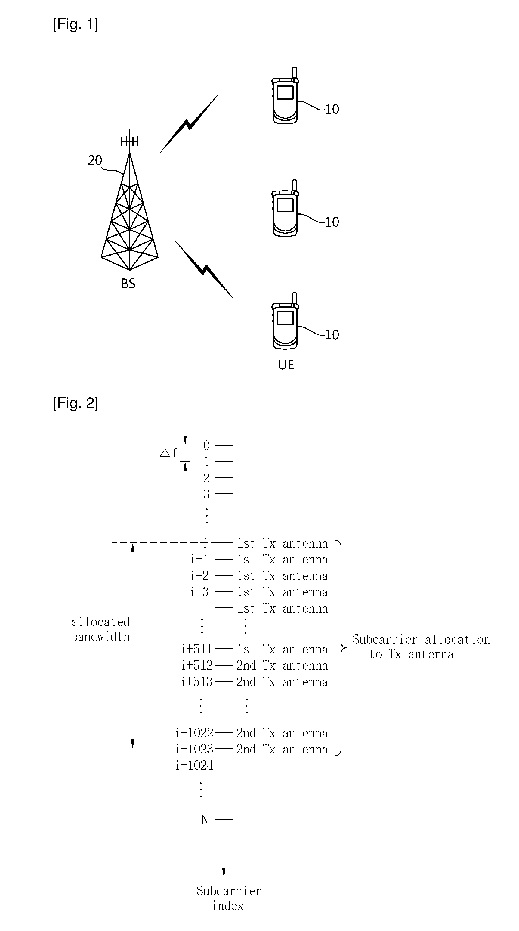
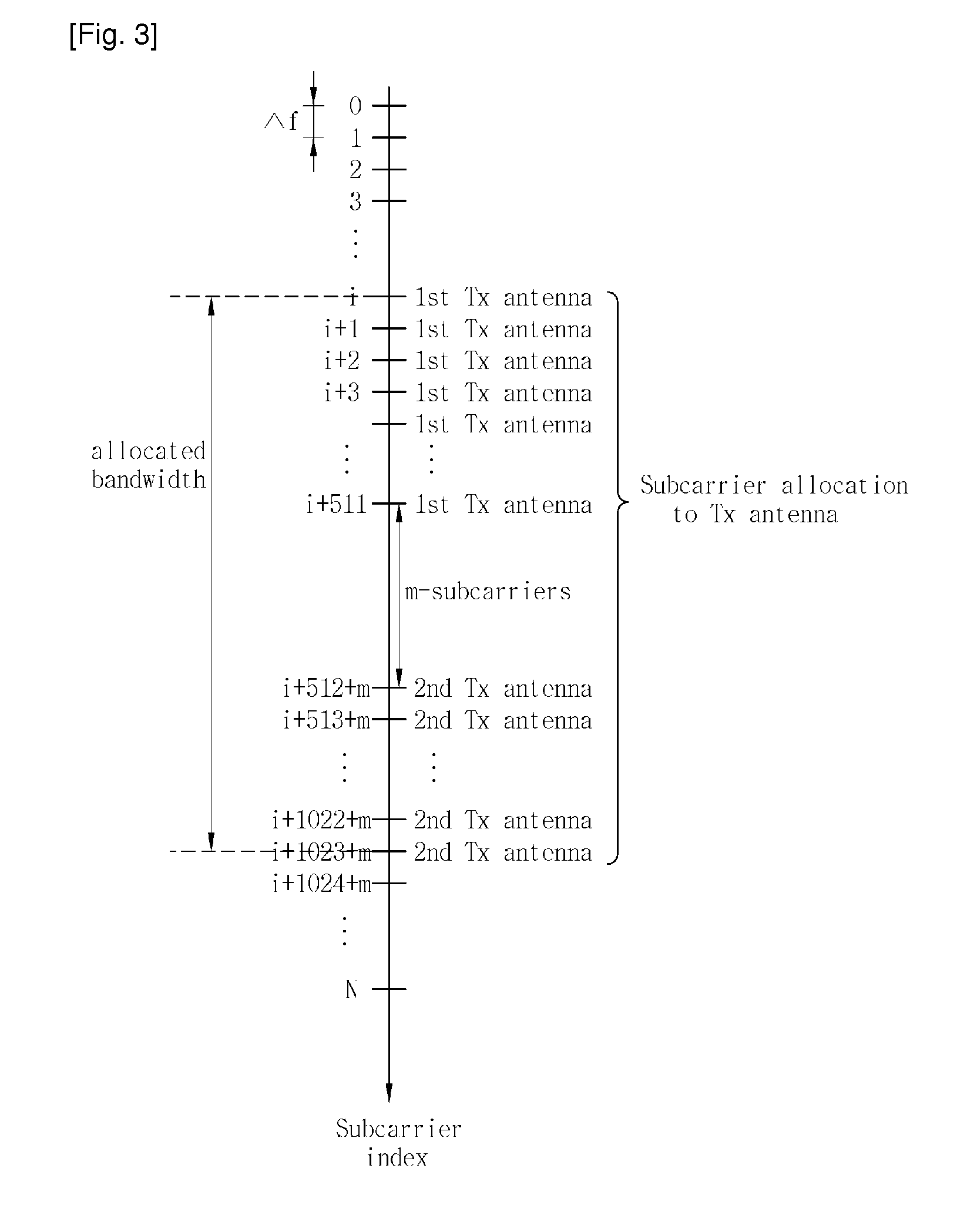
[0037]FIG. 1 shows a wireless communication system. The wireless communication system can be widely deployed to provide a variety of communication services, such as voices, packet data, etc.

[0038]Referring to FIG. 1, the wireless communication system includes at least one user equipment (UE) 10 and a base station (BS) 20. The UE 10 may be fixed or mobile, and may be referred to as another terminology, such as a mobile station (MS), a user terminal (UT), a subscriber station (SS), a wireless device, etc. The BS 20 is generally a fixed station that communicates with the UE 10 and may be referred to as another terminology, such as a node-B, a base transceiver system (BTS), an access point, etc. There are one or more cells within the coverage of the BS 20.

[0039]Hereinafter, a downlink (DL) denotes a communication link from the BS to the UE, and an uplink (UL) denotes a communication link from the UE to the BS. In the DL, a transmitter may be a part of the BS, and a receiver may be a par...


PUM


Abstract

According to an aspect of the present invention, an apparatus for data transmission is provided. The apparatus includes a data processing unit generating a data symbol by performing channel coding and constellation mapping on an information bit, a single carrier-frequency division multiple access (SC-FDMA) modulator generating an SC-FDMA symbol by performing discrete Fourier transform (DFT) on the data symbol, by mapping the DFT performed-data symbol to subcarriers, and by performing inverse fast Fourier transform (IFFT) on the subcarrier mapped-DFT performed-data symbol, and a plurality of transmit antennas transmitting the SC-FDMA symbol. A single carrier-frequency division multiple access (SC-FDMA) system can effectively use frequency switched transmit diversity (FSTD) to reduce a peak-to-average power ratio (PAPR) and to maintain a single-carrier property.

Description

TECHNICAL FIELD[0001]The present invention relates to wireless communications, and more particularly, to an apparatus and method for data transmission by using transmit diversity in a single carrier-frequency division multiple access (SC-FDMA) system with multiple antennas.BACKGROUND ART[0002]Recently, there has been an explosive increase in the demand for wireless data services. Further, an evolution from a wireless voice service to a wireless data service requires a gradual increase of wireless capacity. To cope with such a demand, wireless service providers and wireless equipment manufacturers attempt to improve a data transfer rate of a wireless system, which results in motivating massive researches.[0003]A wireless channel experiences various problems such as path loss, shadowing, fading, noise, limited bandwidth, power limit of a user equipment (UE), and interference between other users. Due to these limitations, the wireless channel has a shape of a narrow pipe that obstructs...

Claims


Application Information

Patent Timeline
23 Jun 2011
Publication
US20110149944A1
IPC
H04B7/208
CPC
H04B7/0617; H04L1/08; H04L27/2614; H04L5/0023; H04L5/0044; H04L1/1671; H04L1/02; H04L27/26
Inventors
KO, HYUN SOO; HAN, SEUNG HEE