Very large mode slab-coupled optical waveguide laser and amplifier

a laser and amplifier technology, applied in the field of very large mode slab coupling optical waveguide lasers, can solve the problems of limiting the power in a single mode, affecting the performance of the amplifier, and becoming more difficult to provide sufficient gain to the fundamental mode,

Active Publication Date: 2011-06-23
MASSACHUSETTS INST OF TECH
View PDF39 Cites 9 Cited by
  • Summary
  • Abstract
  • Description
  • Claims
  • Application Information

AI Technical Summary

Benefits of technology

[0007]According to one aspect of the invention, there is provided very large mode (VLM) slab-coupled optical waveguide laser (SCOWL). The VLM SCOWL includes an upper waveguide region to help guide the laser mode. The upper waveguide region is positioned in the interior regions of the VLM SCOWL. A lower waveguide region also helps to guide the laser mode. The lower waveguide region is positioned in an area underneath the upper waveguide region. An active region is positioned between the upper waveguide region and the lower waveguide region. The active region is arranged so etching into the VLM SCOWL is permitted to define one or more ridge structures leaving the active region unetched. One or more mode control barrier layers are positioned adjacent to the said active region. The one or more mode control barrier layers are used to control the profile of the fundamental mode and prevent mode collapse of the laser mode. They also can be used to block carrier leakage from the active region.
[0008]According to another aspect of the invention, there is provided a very large mode (VLM) slab-coupled optical waveguide laser (SCOWL). The method includes forming an upper waveguide region as part of the waveguide for guiding a laser mode. The upper waveguide region is positioned in the interior regions of the VLM SCOWL. Also, the method includes forming a lower waveguide region as part of the waveguide for guiding the laser mode. The lower waveguide region is positioned in an area underneath the upper waveguide region. Moreover, the method includes positioning an active region between the upper waveguide region and the lower waveguide region. In addition, the method includes arranging the active region so etching into the VLM SCOWL is permitted to define one or more ridge structures leaving the active region unetched. Furthermore, the method includes positioning one or more mode control barrier layers adjacent to the said active region. The one or more mode control barrier layers control the profile of the fundamental mode, prevent mode collapse of the laser mode, and block carrier leakage from the active region.

Problems solved by technology

The power in a single mode is limited by the size of the single-spatial mode in the diode laser.
This is because the maximum power density at the facet is approximately constant, and is limited by effects such as catastrophic optical damage and thermal roll-over.
However, with this simple approach, one finds that it is extremely difficult to filter out higher order modes, since the higher order modes become more numerous as the waveguide dimensions increase and the propagation constants of the higher order modes also become more closely spaced.
In addition, it becomes more difficult to provide sufficient gain to the fundamental mode, while controlling its mode profile.

Method used


Image

  • Very large mode slab-coupled optical waveguide laser and amplifier
  • Very large mode slab-coupled optical waveguide laser and amplifier
  • Very large mode slab-coupled optical waveguide laser and amplifier

Examples


Embodiment Construction

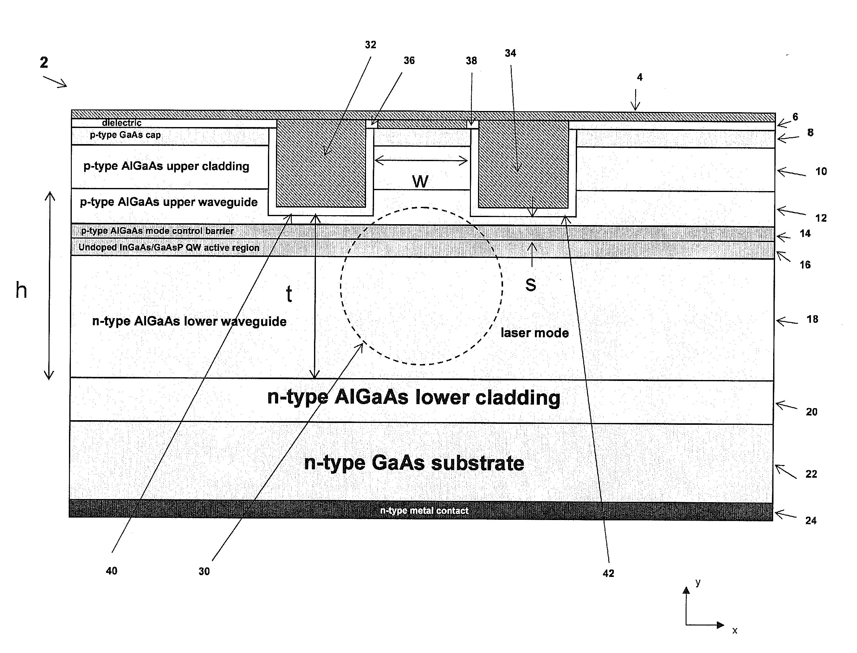
[0014]The invention provides a novel design for a VLM SCOWL to increase its single spatial mode output power. Increasing the output power of the SCOWL is accomplished by an increase of the optical mode size of the fundamental SCOWL mode.

[0015]FIG. 1 shows a cross-sectional view of a VLM SCOWL 2 formed in accordance of the invention. The VLM SCOWL 2 includes a p-type metal layer 4 positioned on a dielectric layer being 6. The dielectric layer 6 is positioned on a p-type GaAs cap layer 8. The VLM SCOWL 2 also includes a p-type upper cladding layer 10 where the p-type GaAs cap layer 8 is positioned on. The p-type upper cladding layer 10 is formed on a p-type AlGaAs upper waveguide region 12. A p-type mode control barrier layer 14 is positioned between the p-type upper waveguide region 12 and an undoped active region 16. The undoped active region 16 is placed on an n-type lower waveguide region 18. The n-type lower waveguide region 18 is positioned on an n-type lower cladding layer 20.

[...


PUM

PropertyMeasurementUnit
thicknessaaaaaaaaaa
thicknessaaaaaaaaaa
thicknessaaaaaaaaaa

Abstract

A very large mode (VLM) slab-coupled optical waveguide laser (SCOWL) is provided that includes an upper waveguide region as part of the waveguide for guiding the laser mode. The upper waveguide region is positioned in the interior regions of the VLM SCOWL. A lower waveguide region also is part of the waveguide that guides the laser mode. The lower waveguide region is positioned in an area underneath the upper waveguide region. An active region is positioned between the upper waveguide region and the lower waveguide region. The active region is arranged so etching into the VLM SCOWL is permitted to define one or more ridge structures leaving the active region unetched. One or more mode control barrier layers are positioned between said upper waveguide region and said lower waveguide region. The one or more mode control barrier layers control the fundamental mode profile and prevent mode collapse of the laser mode. The mode control barrier layers also block carrier leakage from the active region. These layers are essential to obtaining VLM SCOWLs.

Description

SPONSORSHIP INFORMATION[0001]This invention was made with government support awarded by DARPA / MTO under Grant No. FA8721-05-C-0002. The government has certain rights in the invention.BACKGROUND OF THE INVENTION[0002]The invention is related to the field of slab-coupled optical waveguide lasers (SCOWL), and in particular to a very large mode SCOWL.[0003]High power, single spatial mode diode lasers are important for a number of applications, including pumps for fiber lasers and amplifiers and free space optical communications. The power in a single mode is limited by the size of the single-spatial mode in the diode laser.[0004]The state of the art in large spatial mode diode lasers is the SCOWL. A SCOWL device lasing at a wavelength of 1.0 μm designed with a waveguide thickness of 5 μm has been demonstrated to have a stable single spatial mode with dimensions of 5.7 μm (horizontal direction) by 4.5 μm (vertical direction), where these dimensions are given as full width at 1 / e2 intensi...

Claims


Application Information

Patent Timeline
Patent Type & Authority Applications(United States)
IPC IPC(8): H01S3/063B29D11/00
CPCH01S5/0425H01S5/0655H01S5/2004H01S2301/18H01S5/2231H01S5/3211H01S5/2009H01S5/04254H01S2301/176
Inventor HUANG, ROBIN K.DONNELLY, JOSEPH P.
Owner MASSACHUSETTS INST OF TECH
Why Eureka
Try Eureka