Coherent optical receiver system and method for detecting phase modulated signals

Inactive Publication Date: 2011-06-23
UNIV COLLEGE CORK NAT UNIV OF IRELAND CORK
View PDF7 Cites 23 Cited by
  • Summary
  • Abstract
  • Description
  • Claims
  • Application Information

AI Technical Summary

Benefits of technology

[0010]Embodiments of the present invention may enable DSP free detection of optical PSK signals, which may be required in next generation fiber transmission systems and / or optical constellation analyzer systems. In addition, embodiments of the invention may provide improved receiver sensitivity performance compared to direct detection methods. Also, the method may be advantageous in terms of cost and energy efficiency. Avoiding complex and high speed electronic processing the new system may provide simple and low cost means to generate a synchronized local oscillator (LO), which may be required in the homodyne detection process, from a received PSK signal.
[0021]In one embodiment there is provided an adaptive controller circuit to stabilize the operation of the optical injection locked laser.

Problems solved by technology

A high speed DSP solution requires high speed Logic and analogue to digital converters (ADC) which leads to higher power consumption, cost / complexity, and significant investment in ASIC for each generation.
The main drawback is the requirement of low loop delay controllers and very narrow linewidth lasers at the transmitter and receiver which increases the cost and complexity.
The drawback with the heterodyne detection is it has worse receiver sensitivity than homodyne detection and requires high speed electronics and double bandwidth of that required by homodyne detection.
The problem with the methods disclosed in these publications is that they can only work with carrier-based modulation formats (i.e. ASK) and if carrier-less modulation format (i.e. PSK) is to be used, a pilot tone must be transmitted in the orthogonal polarization resulting in worse receiver sensitivity and spectral efficiency.

Method used


Image

  • Coherent optical receiver system and method for detecting phase modulated signals
  • Coherent optical receiver system and method for detecting phase modulated signals
  • Coherent optical receiver system and method for detecting phase modulated signals

Examples


Embodiment Construction

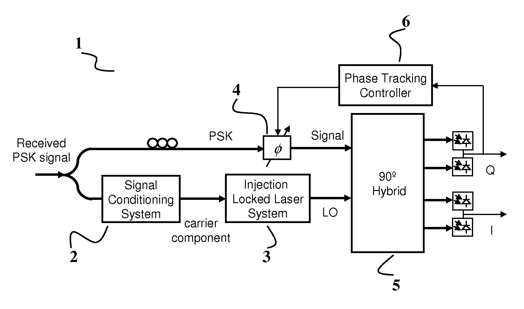
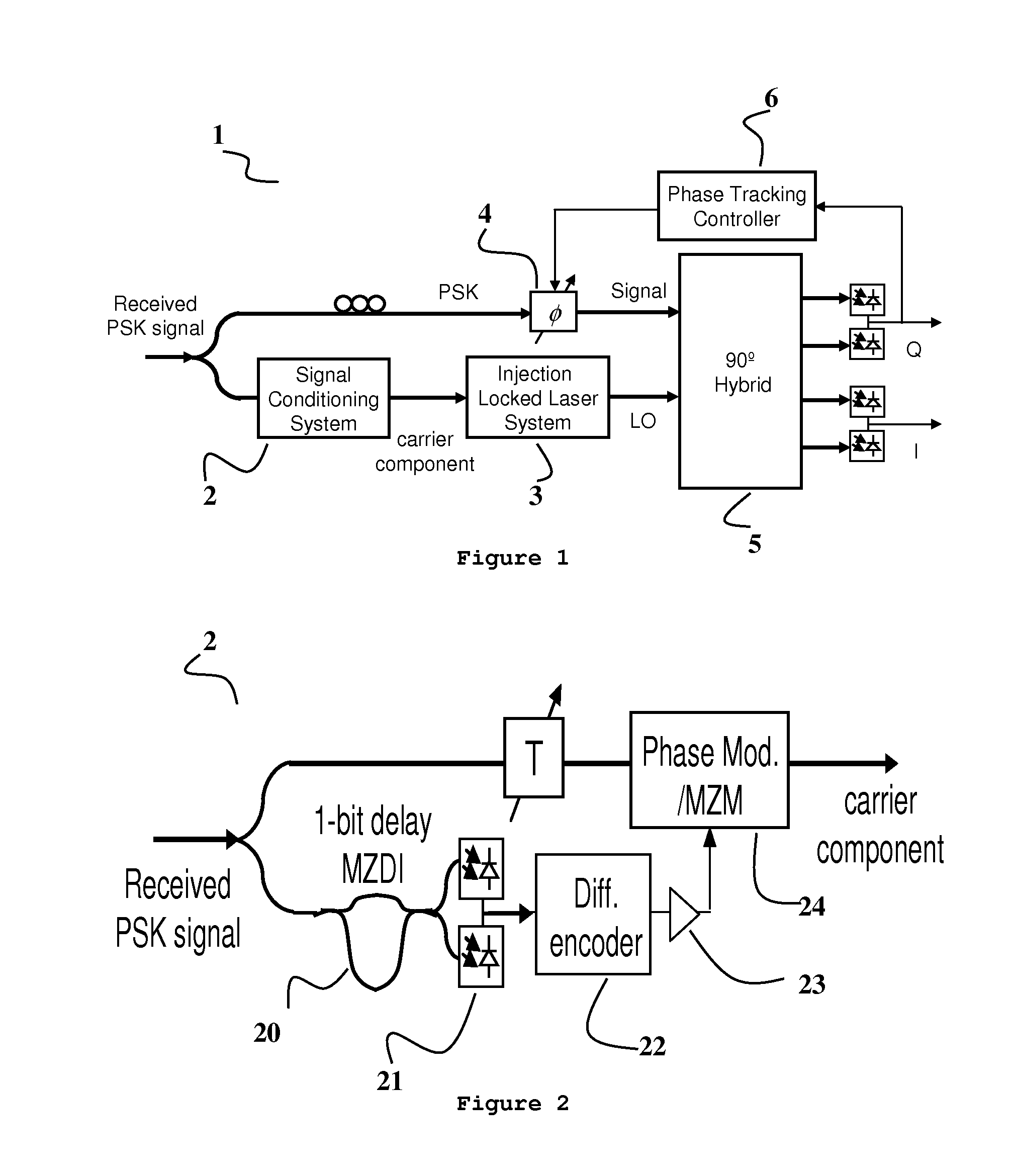
[0040]Referring now to the Figures, and initially FIG. 1, there is illustrated a receiver, suitable for high speed phase shift keying (PSK), indicated generally by the reference numeral 1. A received signal is tapped off and fed into a signal conditioning sub-system 2 that generates a carrier component from the received signal. An optical injection phase locked loop (OIPLL) 3 phase locks the generated carrier component of the incoming signal. A phase tracking system 4 is used to track any environmentally induced slow phase differences between the received signal and the generated LO. A 90° optical hybrid sub-system 5 with an array of balanced photodiodes receives signals from the OIPLL 3 and the phase tracking sub-system 4. The hybrid and photodiodes sub-system 5 is well known in literature of coherent receivers.

[0041]In addition to the three main sub-systems shown in FIG. 1, a low-cost low-power mixed analogue / digital microcontroller 6 may be employed in order to implement all the ...


PUM


Abstract

One aspect of the invention is a homodyne coherent receiver, suitable for high speed phase shift keying (PSK), the receiver comprising a receiver for receiving an incoming signal having a carrier-less modulation format, a signal conditioning sub-system that generates a carrier component from the incoming signal, and an optical injection phase locked loop (OIPLL) that phase locks the generated carrier component of the incoming signal. Embodiments of the invention may enable DSP free detection of optical PSK signals, which may be required in next generation fiber transmission systems and in optical constellation analyzer systems. In addition, embodiments of the invention may provide improved receiver sensitivity performance comparing to prior art systems using direct detection schemes. Also, embodiments of the invention may be advantageous in terms of cost and energy efficiency.

Description

CROSS-REFERENCE TO RELATED APPLICATIONS[0001]This application claims priority under 35 U.S.C. §119 to European Patent App. No. 09177808.4, filed 2 Dec. 2009, which is hereby incorporated by reference in its entirety.BACKGROUND[0002]1. Field[0003]This disclosure generally relates to optical receivers, and in particular, relates to a coherent Optical Receiver that is able to detect carrier-less phase shift keying (PSK) signals using an appropriate carrier recovery technique.[0004]2. Description of the Related Art[0005]Currently commercial solutions for coherent optical receivers make heavy usage of high speed digital signal processing (DSP) to detect the received information. An example of a coherent optical receiver can be found on www.nortel.com. A high speed DSP solution requires high speed Logic and analogue to digital converters (ADC) which leads to higher power consumption, cost / complexity, and significant investment in ASIC for each generation. It also requires error forward er...

Claims


Application Information

Patent Timeline
IPC IPC(8): H04B10/06H04B10/60H04B10/61H04B10/63
CPCH04B10/60H04B10/63H04B10/613
Inventor ELLIS, ANDREWIBRAHIM, SELWAN K.SYGLETOS, STYLIANOS
Owner UNIV COLLEGE CORK NAT UNIV OF IRELAND CORK
Why Eureka
Try Eureka