Blade deflection measurement with magnetostrictive sensor

a magnetostrictive sensor and blade deflection technology, applied in the direction of instruments, marine propulsion, vessel construction, etc., can solve the problems of large dynamic mechanical load on the rotor blade of the wind turbine, large fatigue load in the root, and damage to the rotor blade, so as to achieve accurate determination

Inactive Publication Date: 2011-06-23
SIEMENS GAMESA RENEWABLE ENERGY AS
View PDF11 Cites 12 Cited by
  • Summary
  • Abstract
  • Description
  • Claims
  • Application Information

AI Technical Summary

Benefits of technology

[0035](E) In the described signal receiver the torsion wave, which may have a frequency in the ultrasonic regime, may cause a permeability change of the metal strip according to the inverse magnetostrictive effect (called villary effect). The resulting change of the magnetic field of the fixed permanent magnet on the time scale induces an electric current signal in the detector coil, which is processed by appropriate sensor electronics.
[0036](F) It is mentioned that the torsional ultrasonic wave may travel through the waveguide at constant ultrasonic speed. The position of the second rotor/blade portion can be determined accurately by a travel time measurement, whereby the ...

Problems solved by technology

Rotor blades of wind turbine are exposed to large dynamic mechanical loads in particular when the wind turbine is operated in turbulent wind conditions or in conditions of flow distortion, e.g. high wind shear.
The risk for damaging a rotor blade strongly depends on the fatigue the blade is currently suffering and on the fatigue life time, which the rotor blade has accumulated so far during its previous operation.
If the rotor blade has a large deflection the fatigue load in the root is relatively big.
However, continuing load cycles of rotor blades cause a big wear of such strain g...

Method used


Image

  • Blade deflection measurement with magnetostrictive sensor
  • Blade deflection measurement with magnetostrictive sensor
  • Blade deflection measurement with magnetostrictive sensor

Examples


Embodiment Construction

[0056]The illustration in the drawing is schematically. It is noted that in different figures, similar or identical elements are provided with the same reference signs or with reference signs, which are different from the corresponding reference signs only within the first digit.

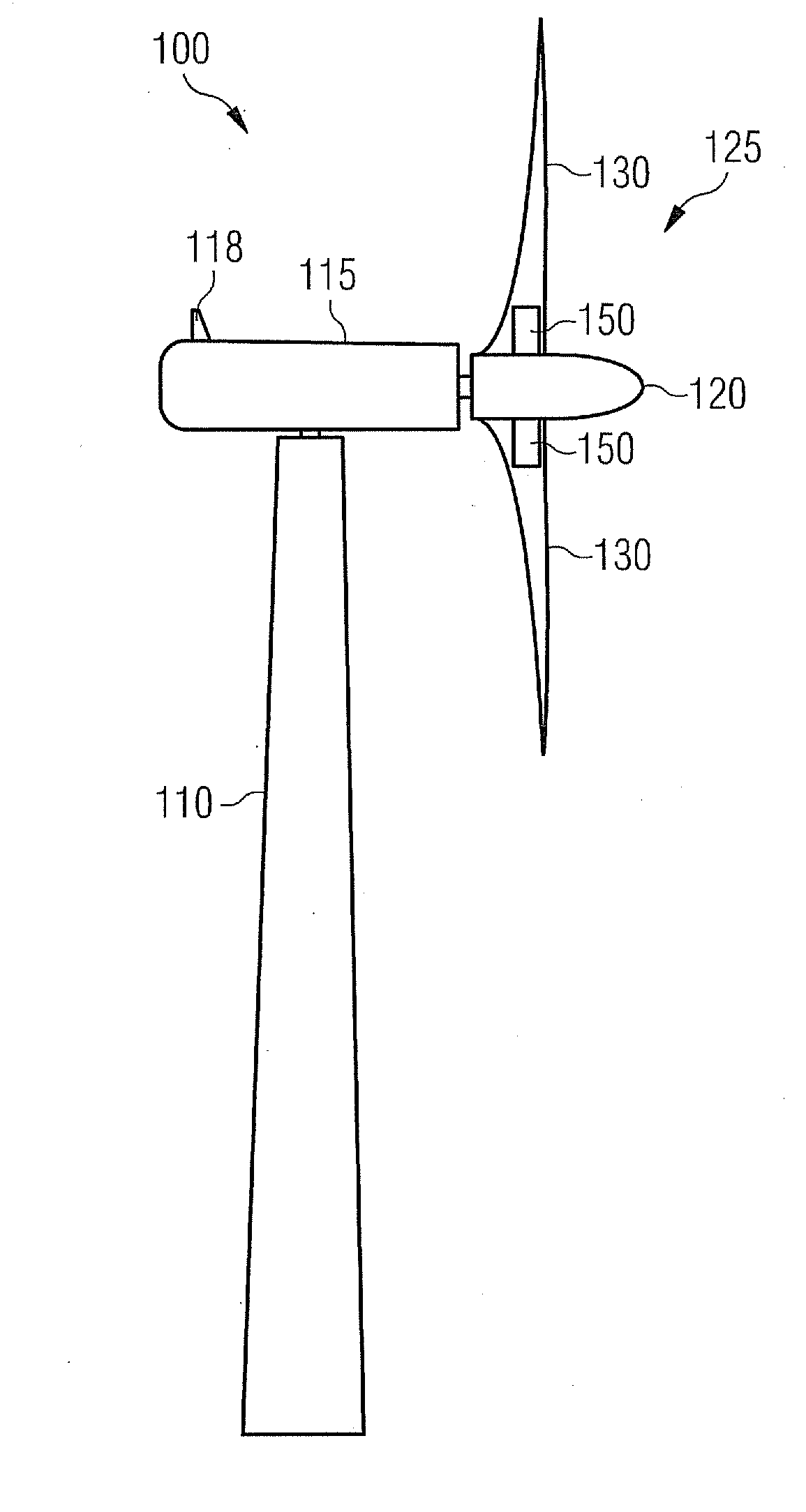
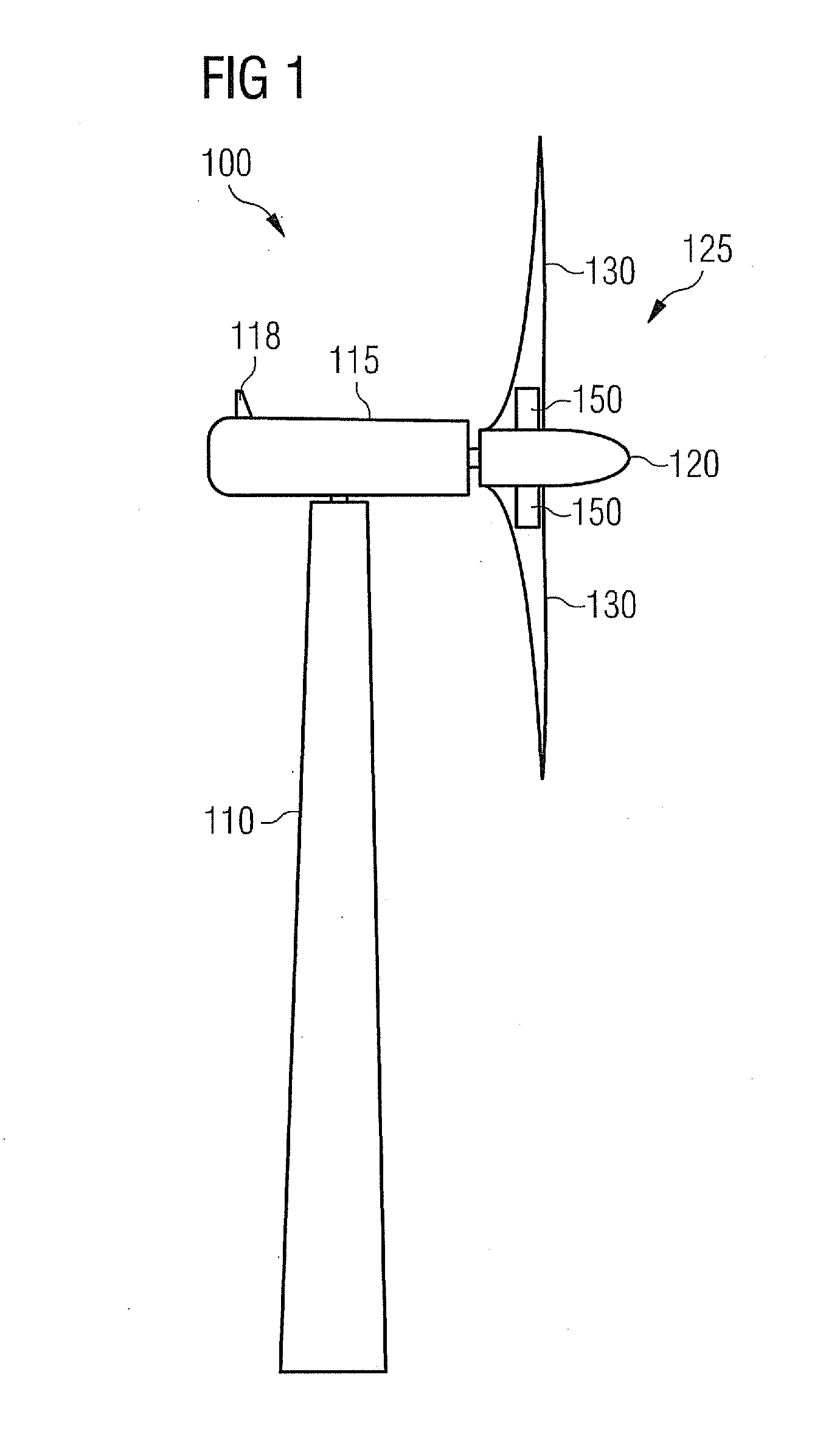
[0057]FIG. 1 shows a wind turbine 100 comprising a tower 110 and a nacelle 115, which is mounted pivotally at a top portion of the tower 110. The nacelle is equipped with a weather station 118, which may comprise for instance a wind measurement sensor (not depicted) for determining the wind speed and the wind direction. A precise knowledge of the wind speed and / or of the wind direction may be useful for operating the wind turbine in an appropriate manner.

[0058]The wind turbine further comprises a rotor 125. According to the embodiment described here the rotor 125 comprises two blades 130, which are mounted to a hub 120 of the rotor 125. Each blade 130 is provided with a magnetostrictive measurement arrangeme...


PUM


Abstract

A measurement arrangement for measuring a deflection of a wind turbine rotor blade is provided. The measurement arrangement includes a magnetostrictive sensor, which includes a first sensor part and a second sensor part, a first support structure, which is adapted to be mounted to a first portion of the rotor, wherein the first sensor part is mounted to the first support structure, and a second support structure, which may be mounted to a second portion of the rotor, wherein the second sensor part is mounted to the second support structure and wherein either or both the first portion and the second portion is a portion of the blade. The magnetostrictive sensor measures the relative spatial position between the first sensor part and the second sensor part. A method for measuring a blade deflection and a wind turbine rotor which includes the described blade deflection measurement arrangement are also provided.

Description

CROSS REFERENCE TO RELATED APPLICATIONS[0001]This application claims priority of European Patent Office application No. 09015863.5 EP filed Dec. 22, 2009, which is incorporated by reference herein in its entirety.FIELD OF INVENTION[0002]The present invention relates to the technical field of measuring and controlling mechanical loads which are acting on a rotor blade of a wind turbine. Specifically, the present invention relates to a measurement arrangement and to a method for measuring a deflection of a blade of a rotor of a wind turbine. Further, the present invention relates to wind turbine rotor and to a wind turbine which comprise the described blade deflection measurement arrangement.ART BACKGROUND[0003]Rotor blades of wind turbine are exposed to large dynamic mechanical loads in particular when the wind turbine is operated in turbulent wind conditions or in conditions of flow distortion, e.g. high wind shear. Therefore, the rotor blades of wind turbines and the corresponding ...

Claims


Application Information

Patent Timeline
IPC IPC(8): F03D11/00G01L3/10
CPCF05B2280/5008Y02E10/721Y02E10/722F05B2270/331F05B2270/808F03D11/0091F03D17/00Y02E10/72
Inventor ANDERSEN, JIMMIEGEDAL, PER
Owner SIEMENS GAMESA RENEWABLE ENERGY AS
Why Eureka
Try Eureka