Multiple envelope tracking system for an active antenna array

a tracking system and antenna array technology, applied in the field of active antenna arrays, can solve the problems of linear power amplification compromising the energy efficiency of the overall system, radio frequency, and become an issue for the infrastructure of communication networks, and achieve the effect of improving linearity and/or power efficiency

Active Publication Date: 2011-06-23
TELEFON AB LM ERICSSON (PUBL)
View PDF7 Cites 59 Cited by
  • Summary
  • Abstract
  • Description
  • Claims
  • Application Information

AI Technical Summary

Benefits of technology

[0034]The amplifiers of the plurality of transmission paths may be Doherty-amplifiers. Doherty-amplifiers are actually an alternative solution to envelope tracking since they also attempt to reconcile power efficiency and linearity. However, it is also possible to combine the two concepts in order to further improve the linearity and / or the power efficiency.

Problems solved by technology

While the power efficiency was practically always important for battery-powered devices, it has also become an issue for the infrastructure of communication networks.
Linear power amplification compromises overall system energy efficiency because radio frequency (RF) power amplifiers (PAs) are less efficient when they are operated at a power level that is below the power amplifier's maximum power (backed-off operating mode).
It has been estimated that the power amplifier and its associated components consume up to 50% of the overall power in a cellular base station.
Linearity and power efficiency tend to contradict each other.

Method used


Image

  • Multiple envelope tracking system for an active antenna array
  • Multiple envelope tracking system for an active antenna array
  • Multiple envelope tracking system for an active antenna array

Examples


Embodiment Construction

[0063]The invention will now be described on the basis of the drawings. It will be understood that the embodiments and aspects of the invention described herein are only examples and do not limit the protective scope of the claims in any way. The invention is defined by the claims and their equivalence. It will be understood that features of one aspect can be combined with a feature of a different aspect or aspects.

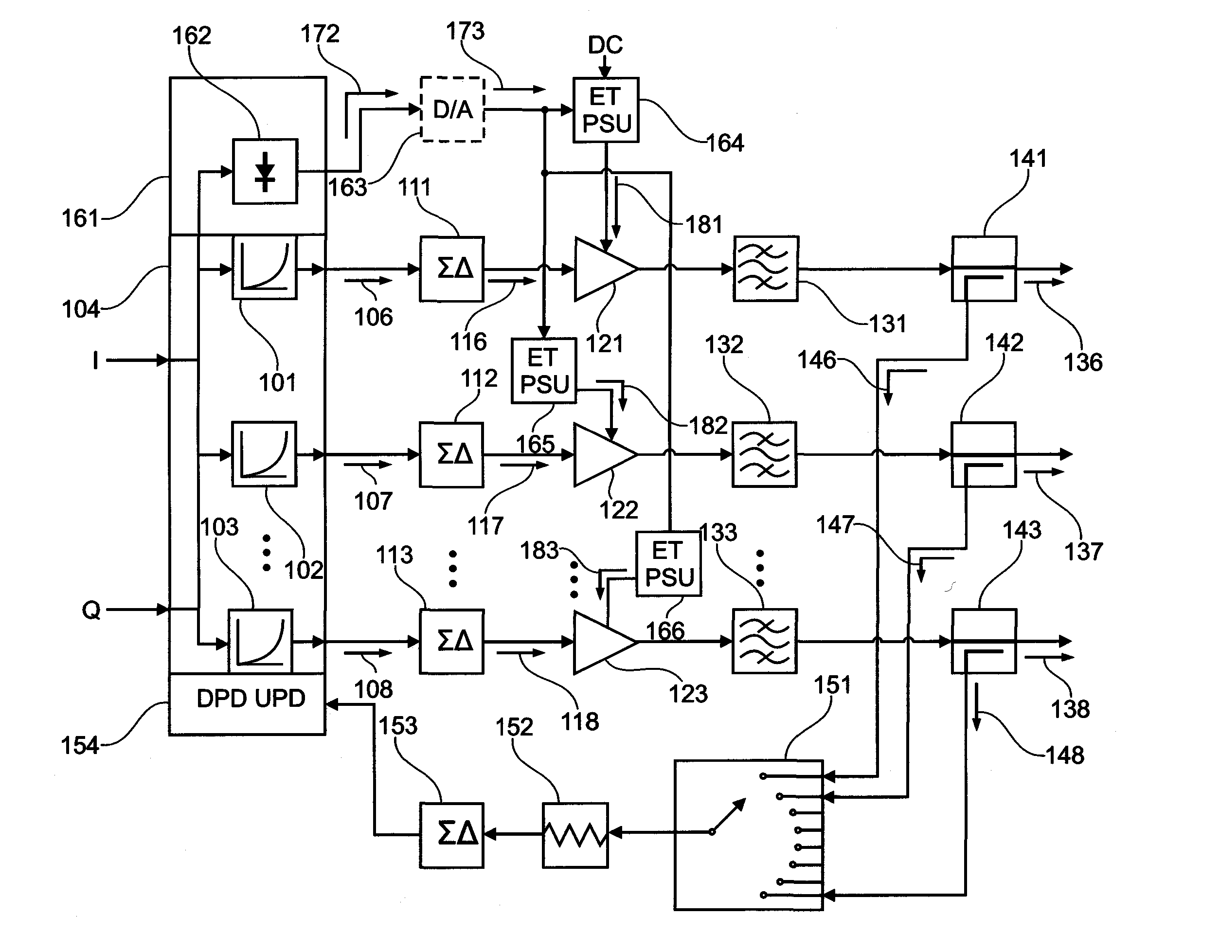
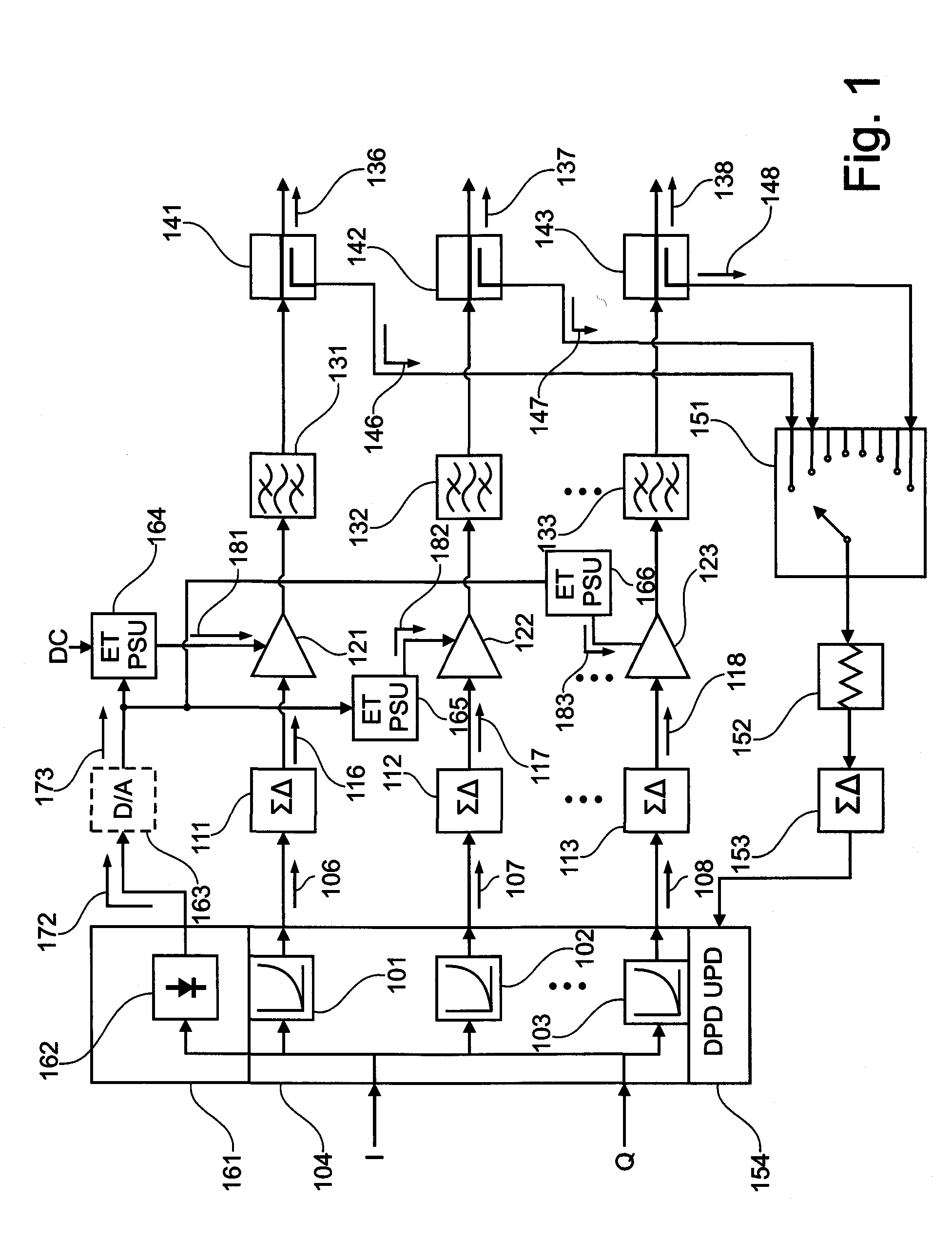
[0064]FIG. 1 shows a schematic block diagram of an active antenna array according to a first possible configuration. The active antenna array comprises a plurality of transmission paths, three of which are illustrated in FIG. 1.

[0065]A signal to be transmitted reaches the active antenna array from the left. In FIG. 1 the signal to be transmitted is illustrated as comprising an in-phase component I and a quadrature component Q. The signal to be transmitted may be present at a baseband frequency range, an intermediate frequency (IF) range, or at a radio frequency (RF) range...


PUM


Abstract

An active antenna array comprises a plurality of transmission paths, a plurality of variable power supply units, and an envelope detection system. The transmission paths are adapted to carry a plurality of similar transmission path signals, and the plurality of transmission paths comprises an amplifier having a power input and a signal input for one of the plurality of similar transmission path signals. The plurality of variable power supply units is connected to the power input of the amplifier for supplying power to the amplifiers. Each of the plurality of variable power supply units comprises an envelope signal input. The envelope detection system is connected to the envelope inputs of the plurality of variable power supply units and adapted to provide a common envelope signal for the plurality of similar transmission path signals to the plurality of variable power supply units. A method for envelope tracking and computer program products for manufacture and method execution are also claimed.

Description

CROSS REFERENCE TO OTHER APPLICATION[0001]The present application is related to U.S. patent application Ser. No. ______ entitled “Single Envelope Tracking System for an Active Antenna Array” (Attorney's Docket No. 4424-P04958US0) filed concurrently herewith. The entire disclosure of the foregoing application is incorporated herein by reference.FIELD OF THE INVENTION[0002]The field of the present invention relates to an active antenna array and the processing of envelopes of signals in or by the active antenna array. The field of the present invention further relates to a method for performing envelope tracking on a plurality of amplifiers that amplify a plurality of similar transmission path signals.BACKGROUND OF THE INVENTION[0003]In the design of radio transmission systems, one of the desires that have to be addressed is power efficiency. While the power efficiency was practically always important for battery-powered devices, it has also become an issue for the infrastructure of c...

Claims


Application Information

Patent Timeline
Patent Type & Authority Applications(United States)
IPC IPC(8): H04B1/04
CPCH01Q3/28H03F1/0227H03F1/0288H03F1/3247H03F3/195H03F3/24Y02B60/50H03F2200/102H03F2200/336H03F2200/451H03F2200/504H04W52/42H03F3/68H01Q3/2605H04B7/0408H04B7/0619H04B7/0897H04L27/2601
Inventor KENINGTON, PETER
Owner TELEFON AB LM ERICSSON (PUBL)
Why Eureka
Try Eureka