Ground fault detection system and method

a ground fault and detection system technology, applied in the direction of power supply testing, testing circuits, instruments, etc., can solve the problems of increasing the size and associated material, and affecting the accuracy of ground fault detection results

Active Publication Date: 2011-06-23
ROCKWELL AUTOMATION TECH
View PDF10 Cites 26 Cited by
  • Summary
  • Abstract
  • Description
  • Claims
  • Application Information

AI Technical Summary

Problems solved by technology

A ground fault may have occurred if substantially high current leaks into ground instead of the load.
However, existing ground fault detection circuits may have undesirable effects.
For example, some systems rely on a large number of inductors and windings that may increase t...

Method used


Image

  • Ground fault detection system and method
  • Ground fault detection system and method
  • Ground fault detection system and method

Examples


Embodiment Construction

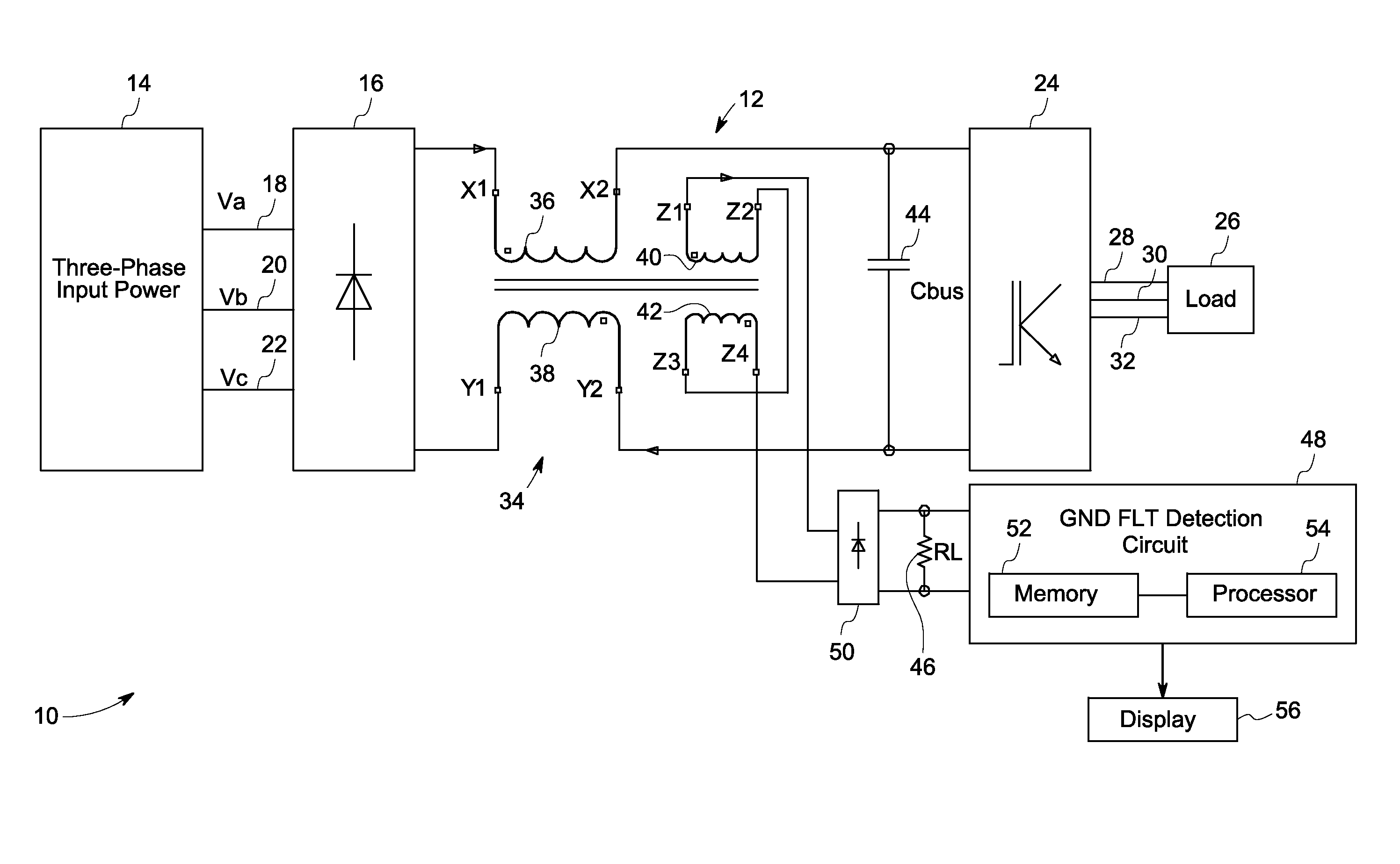
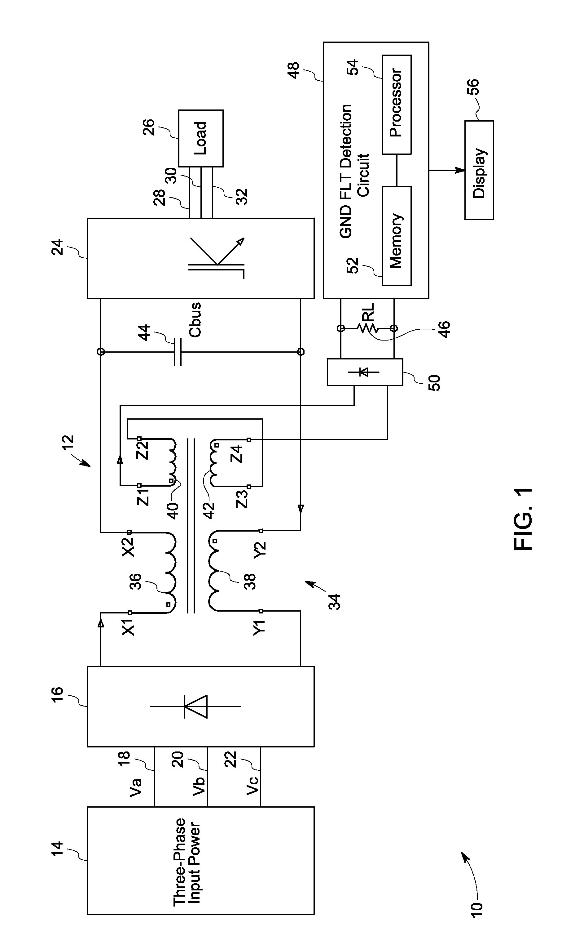
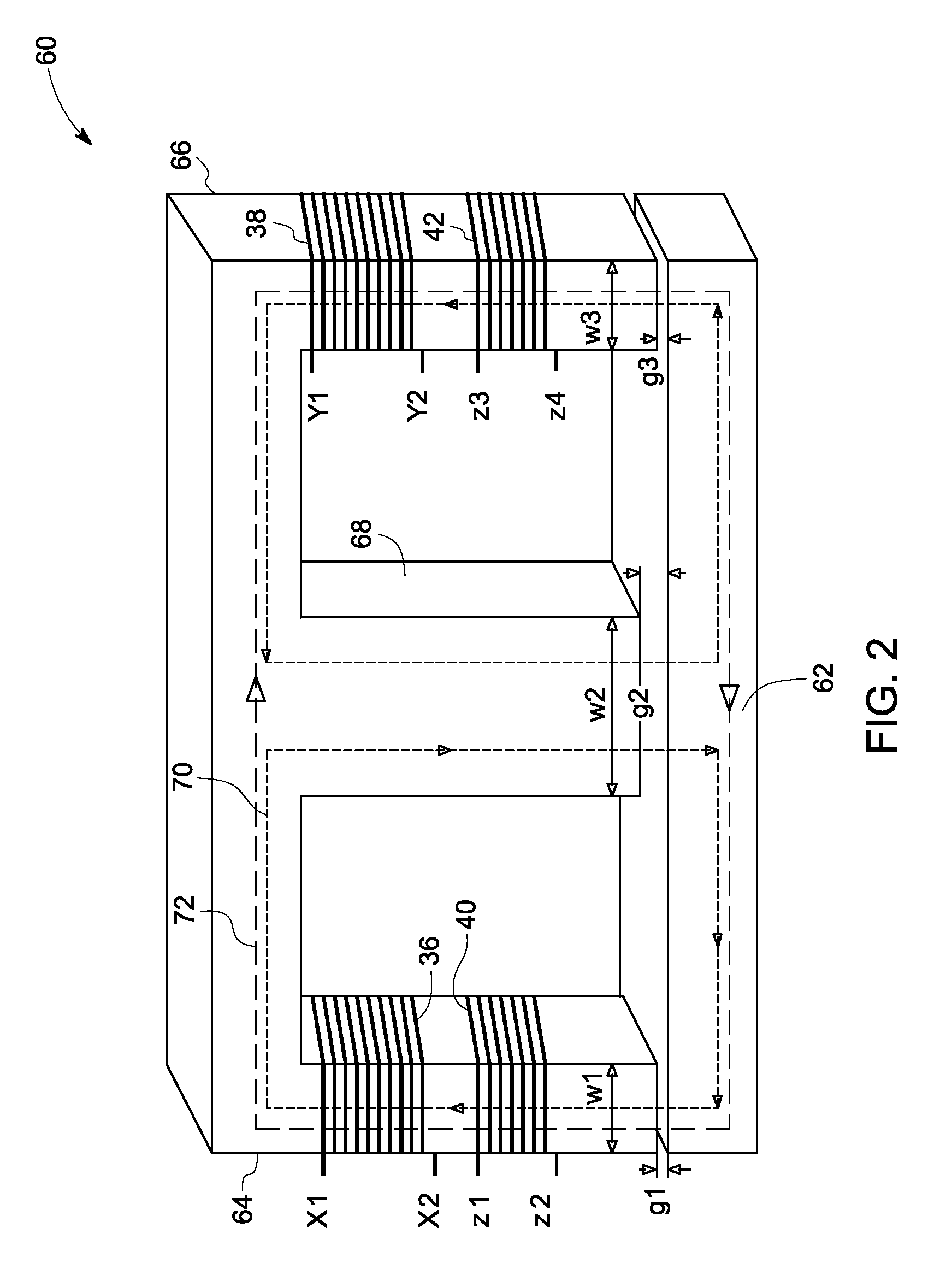
[0013]As discussed in detail below, embodiments of the present technique function to provide a ground fault detection system for detecting ground faults in motor drive and other electrical systems. In particular, the present technique provides an integrated DC link inductor that detects the ground fault without generating excessive voltage in the system during ground fault detection and surge operations.

[0014]References in the specification to“one embodiment”, “an embodiment”, “an exemplary embodiment”, indicate that the embodiment described may include a particular feature, structure, or characteristic, but every embodiment may not necessarily include the particular feature, structure, or characteristic. Moreover, such phrases are not necessarily referring to the same embodiment. Further, when a particular feature, structure, or characteristic is described in connection with an embodiment, it is submitted that it is within the knowledge of one skilled in the art to affect such feat...


PUM


Abstract

A ground fault detection system is provided. The ground fault detection system includes a magnetic core having first and second primary legs and a secondary leg disposed between the first and second primary legs. The ground fault detection system also includes first and second primary windings disposed around the first and second primary legs respectively and configured to introduce current in the first and second primary legs. Further, the ground fault detection system includes first and second secondary windings disposed around the first and second primary legs respectively and configured to detect a ground fault based upon a magnetic flux generated in response to the introduced current.

Description

BACKGROUND[0001]The invention relates generally to a ground fault detection system and methods for ground fault detection.[0002]A wide range of equipment, such as electric motor drives, are known and are in use for a variety of applications, such as in factory automation systems, power generation systems and so forth. Typically a load is connected to a power source, such as a drive in the case of a motor, which provides electrical power to the load in a controlled manner. In alternating current (AC) motor drive systems, for example, electrical power is converted from an AC power source into direct current (DC) voltage. The DC voltage is then converted via an inverter into AC voltage with controlled frequency and amplitude which may be applied to drive the electric motor. Other loads are provided with power in similar ways, with converters of various types providing controlled frequency AC power, either at a fixed frequency or a controlled variable frequency (e.g., for regulating the...

Claims


Application Information

Patent Timeline
IPC IPC(8): G01R31/00G01R31/14
CPCH02H1/0007H02H7/1222H02H3/332G01R15/183H02M5/458G01R31/42G01R31/52H02M1/0009H02M1/123
Inventor WINTERHALTER, CRAIG R.WEI, LIXIANGVRANKOVIC, ZORAN V.
Owner ROCKWELL AUTOMATION TECH
Why Eureka
Try Eureka