
Integrated microelectromechanical gyroscope with improved driving structure

a microelectromechanical and driving structure technology, applied in the direction of turning-sensitive devices, instruments, manufacturing tools, etc., can solve the problems of complex design and implementation of microelectromechanical gyroscopes, and achieve the effect of improving electromechanical characteristics

Active Publication Date: 2011-06-30
STMICROELECTRONICS SRL
View PDF45 Cites 86 Cited by
  • Summary
  • Abstract
  • Description
  • Claims
  • Application Information

AI Technical Summary

Benefits of technology

[0011]The present disclosure is directed to a microelectromechanical gyroscope with improved electromechanical characteristics, in particular as regards the corresponding driving structure.

Problems solved by technology

It is hence evident that design and implementation of a microelectromechanical gyroscope are particularly complex, both as regards the micromechanical part and as regards the associated driving and reading electronics.
In addition, it is generally complex to maintain the desired ratios between frequency, phase, and amplitude of the oscillations of the driving masses in the various driving directions.

Method used


Image

  • Integrated microelectromechanical gyroscope with improved driving structure
  • Integrated microelectromechanical gyroscope with improved driving structure
  • Integrated microelectromechanical gyroscope with improved driving structure

Examples


first embodiment

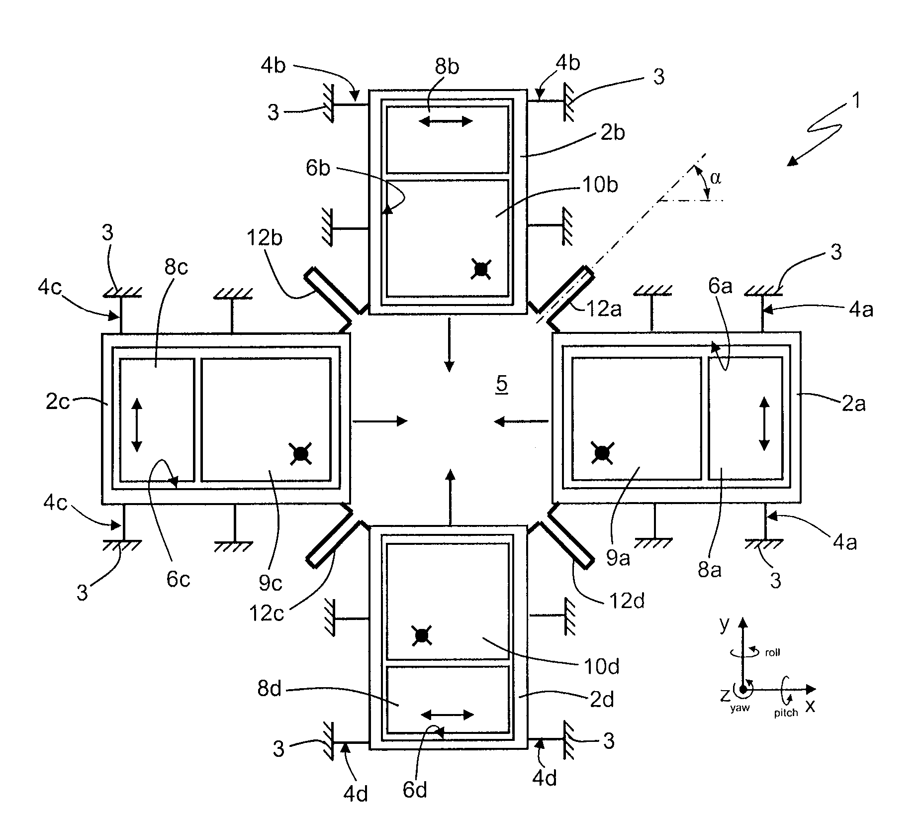
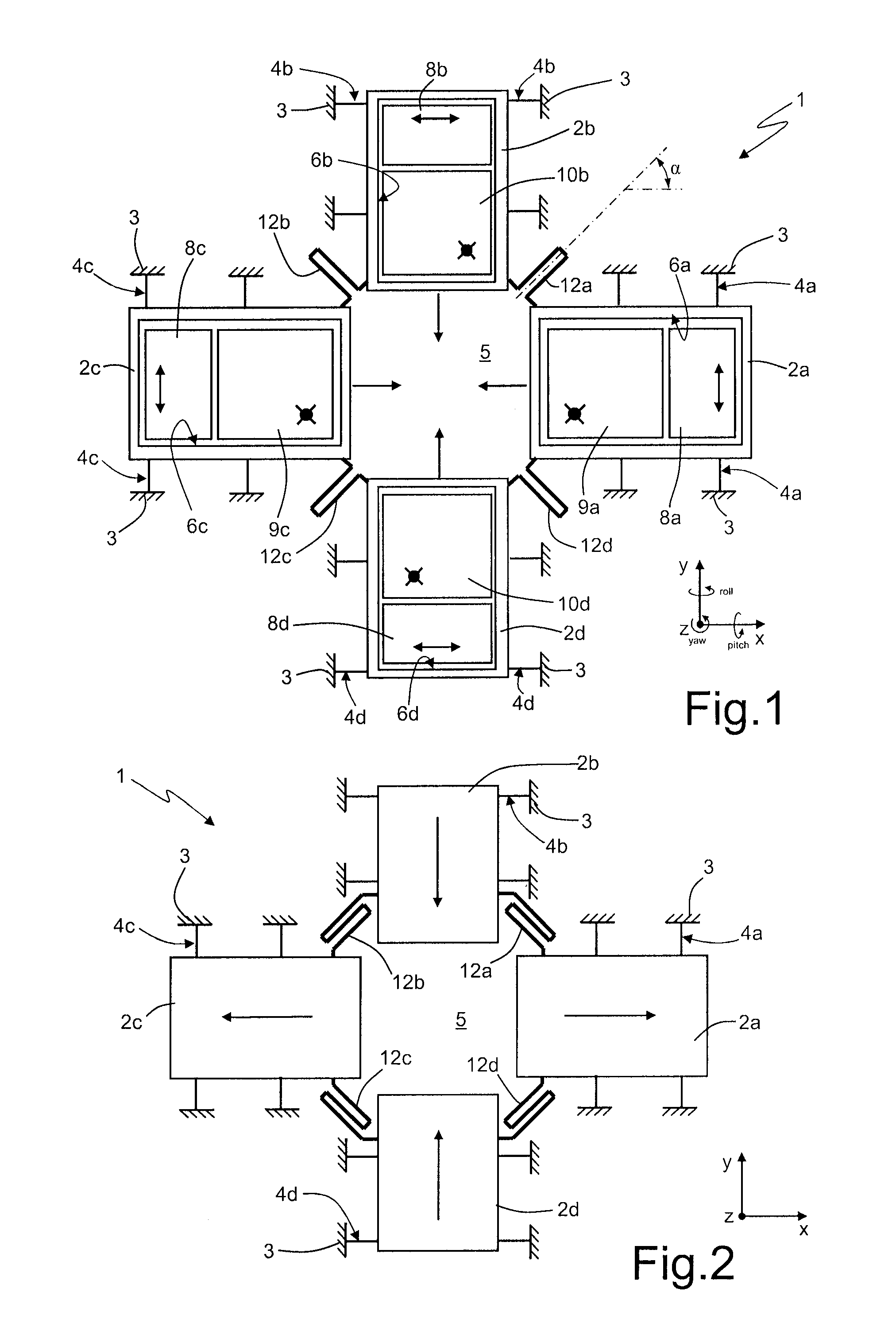
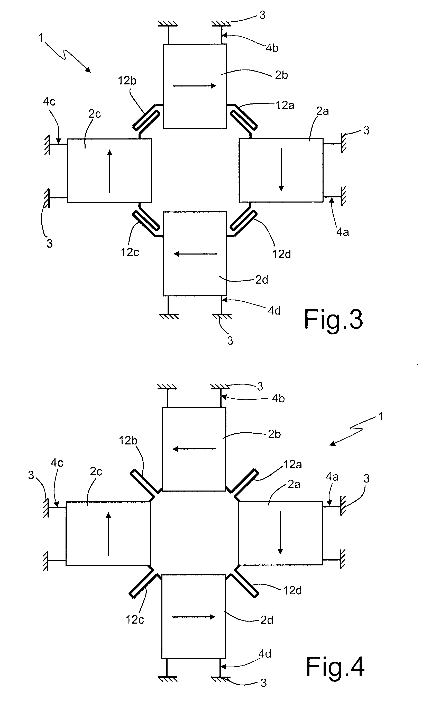
[0040]As illustrated in FIG. 5, in the MEMS gyroscope 1 the driving masses 2a-2d have a frame conformation, shaped like a “U” or like a “U” turned over or upside down, defining inside them a respective housing opening 6a-6d, open towards the empty space 5, which is set centrally with respect to the entire micromechanical structure. Each driving mass 2a-2d is anchored to an underlying substrate (here not illustrated) of the MEMS gyroscope 1 by means of a pair of elastic anchorage elements 4a-4d, of the folded type, designed to enable movement only in the respective driving direction. The driving masses 2a-2d are moreover coupled to one another by means of the elastic coupling elements 12a-12d, substantially according to the scheme described for the micromechanical structure of FIG. 1.

[0041]A respective assembly 13 of driving electrodes is coupled to the first and third driving masses 2a, 2c to cause driving movement thereof along the first axis x (it is in any case evident that, alte...

third embodiment

[0056]A third embodiment, illustrated in FIG. 7, once again envisages that at least some of the driving masses (for example, the second and fourth driving masses 2b, 2d) coincide with the sensing masses (substantially as described with reference to FIG. 6), and moreover envisages decoupling of the driving electrodes from the sensing masses in such a way as to reduce the driving disturbance on the reading of the angular velocity to be measured (for example the yaw angular velocity), albeit generating the desired force in the driving direction.

[0057]In the MEMS gyroscope, here designated by 1″, the first and third driving masses 2a, 2c (which have, for example, a full rectangular shape in the horizontal plane xy) are connected to the respective first and third sensing masses 9a, 9c by means of elastic decoupling elements 32, having an axis of extension oriented along the first horizontal axis x. The elastic coupling elements 12a-12d are in this case directly connected to the first and...


PUM

PropertyMeasurementUnit
Angleaaaaaaaaaa
Massaaaaaaaaaa
Ratioaaaaaaaaaa

Abstract

An integrated MEMS gyroscope, is provided with: at least a first driving mass driven with a first driving movement along a first axis upon biasing of an assembly of driving electrodes, the first driving movement generating at least one sensing movement, in the presence of rotations of the integrated MEMS gyroscope; and at least a second driving mass driven with a second driving movement along a second axis, transverse to the first axis, the second driving movement generating at least a respective sensing movement, in the presence of rotations of the integrated MEMS gyroscope. The integrated MEMS gyroscope is moreover provided with a first elastic coupling element, which elastically couples the first driving mass and the second driving mass in such a way as to couple the first driving movement to the second driving movement with a given ratio of movement.

Description

BACKGROUND[0001]1. Technical Field[0002]The present disclosure relates to an integrated microelectromechanical gyroscope, in particular of a triaxial type, with an improved driving structure.[0003]2. Description of the Related Art[0004]As is known, current micromachining techniques enable production of microelectromechanical systems (MEMS) starting from layers of semiconductor material, which have been deposited (for example, a layer of polycrystalline silicon) or grown (for example, an epitaxial layer) on sacrificial layers, which are removed via chemical etching. Inertial sensors, accelerometers and gyroscopes obtained with this technology are encountering an increasing success, for example, in the automotive field, in inertial navigation, or in the field of portable devices.[0005]In particular, integrated gyroscopes made of semiconductor material obtained with MEMS technology are known. These gyroscopes operate based on the theorem of relative accelerations, exploiting the Coriol...

Claims


Application Information

Patent Timeline
IPC IPC(8): G01C19/56B23P11/00
CPCG01C19/5747Y10T29/49826G01P9/02
Inventor CAZZANIGA, GABRIELECORONATO, LUCA
Owner STMICROELECTRONICS SRL
Features
  • Generate Ideas
  • Intellectual Property
  • Life Sciences
  • Materials
  • Tech Scout
  • Unparalleled Data Quality
  • Higher Quality Content
  • 60% Fewer Hallucinations
Learn More