Piston for an Internal-Combustion Engine and Method for Manufacturing a Piston of this Type

a technology of internal combustion engine and piston, which is applied in the direction of engine components, machines/engines, mechanical apparatus, etc., can solve the problems of considerable thermal load on the heads of the pistons inserted therein, complex assembly of the known piston, and inability to allow considerable production costs, etc., to achieve good sliding properties, less force, and deformation

Inactive Publication Date: 2011-06-30
THYSSENKRUPP METALURGICA CAMPO LIMPO
View PDF22 Cites 8 Cited by
  • Summary
  • Abstract
  • Description
  • Claims
  • Application Information

AI Technical Summary

Benefits of technology

[0022]A further important advantage of the invention lies in the simple possibility of being able to combine even the most diverse materials without difficulty. The invention thus allows, for example, the piston head part to be made of a high-strength stainless steel and the piston skirt part to be made of a steel that is less strong but is particularly deformable or has particularly good sliding properties. It is also possible to combine a piston head part made of steel (in particular stainless steel) with a piston skirt part made of light metal, such as aluminum.
[0023]The connection of the two piston parts, produced in accordance with the invention via at least one press fit, also allows the press fit to be formed in each case at the location at which it has an optimum effect with regard to the loads occurring during practical operation. The press fit can thus be formed, for example, in the region of the piston wall forming the outer delimitation of the cooling chamber. A press fit of this type, arranged peripherally in the region of the circumference of the piston, reliably minimizes the risk of opening of the joint seam, which is inevitably present between the first and the second part of a piston according to the invention.
[0024]Alternatively or additionally, it can also be expedient to form the press fit in a centrally arranged region of the piston. In this embodiment, the comparatively high thicknesses of the walls present in the central region of the piston allow particularly high pressures to be generated between the molded elements of the piston skirt and piston head part, via which the positive and non-positive connection according to the invention is produced. A particularly operationally secure connection of the two parts of a piston according to the invention is obtained, in this case, if the central pressed fit and the peripheral, outer press fit are combined with each other.
[0025]The at least one cooling chamber of the piston according to the invention can be a single integral cooling chamber formed in the center of the piston or a cooling channel which surrounds the center of the piston. It is also possible to combine a first cooling chamber placed in the center of the piston and a second cooling chamber in the form of a channel surrounding the central cooling chamber. By the presence of a centrally placed cooling chamber the transfer of heat from the combustion chamber of the engine to the piston skirt is interrupted, or at least decisively limited, so that the surface temperature of the combustion cavity of the piston rises. Accordingly, the combustion of fuel in the combustion chamber of the engine takes place at high temperatures, so that the chemical energy of the fuel can be used with a higher efficiency.
[0026]In principle, it is possible to configure a plurality of cooling chambers in the piston head part or in the piston skirt part of a piston according to the invention in order to achieve maximum cooling effect. If the press fit is formed in the central region of the piston, it is particularly possible to guide a cooling chamber formed as a cooling channel of maximum cross section around the central region. If a press fit between the two parts is additionally formed in the outer peripheral region of the piston, the permanent tightness of the press fit can be reliably ensured.
[0027]A simple press fit between the first and second part can be provided by forming into the side of the one part that is associated with the other part, as a recess, a peripheral groove in which, as a projection, a likewise peripheral shoulder of the second part is held positively and non-positively in a press fit.

Problems solved by technology

However, considerable production costs have to be allowed for.
In the case of highly stressed diesel engines or highly charged spark-ignition engines, the heads of the pistons inserted therein are exposed to considerable thermal loads.
Although the multi-part construction of the known piston allows the cooling channel to be manufactured in a simple manner, the assembly of the known piston is complex.
The inevitable arrangement of the screw heads of the connecting screws in the combustion cavity of the piston head part also restricts the freedom of the design of a piston of this type.
This type of connection not only presupposes a specific configuration of the faces brought into contact with one another for welding but also restricts the choice of materials of which the piston is composed.
Thus, in this known piston it is not possible to make the piston head upper part (which is in practice subjected to high loads) of a steel material and the piston head lower part (which is subjected to lower loads) from a light material in order to save weight.
Although a multi-part construction of this type allows complex shaping of the piston formed from two parts, apart from the load-capacity problems resulting from the multi-part construction, the production costs associated therewith are considerable.

Method used


Image

  • Piston for an Internal-Combustion Engine and Method for Manufacturing a Piston of this Type
  • Piston for an Internal-Combustion Engine and Method for Manufacturing a Piston of this Type
  • Piston for an Internal-Combustion Engine and Method for Manufacturing a Piston of this Type

Examples


Embodiment Construction

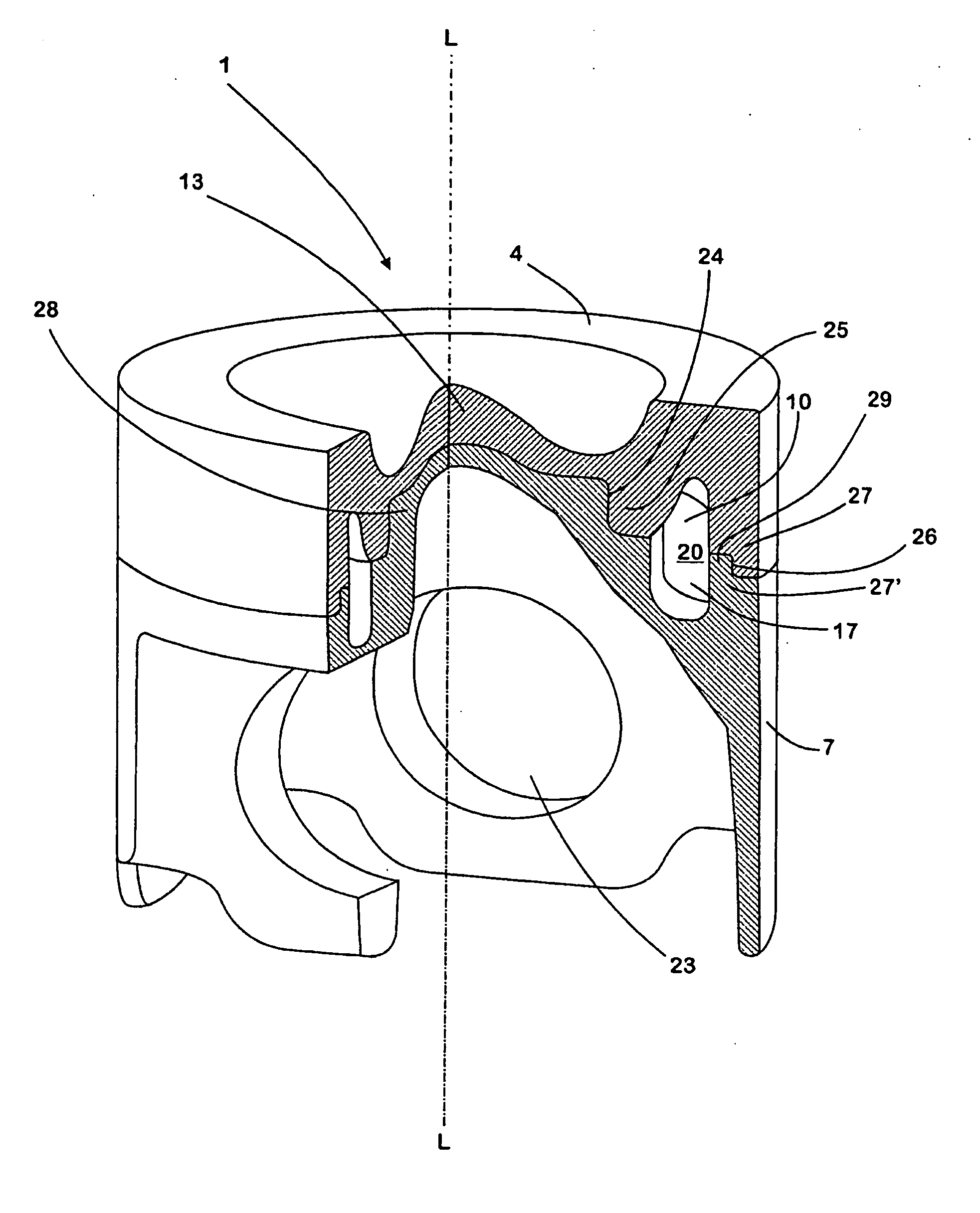
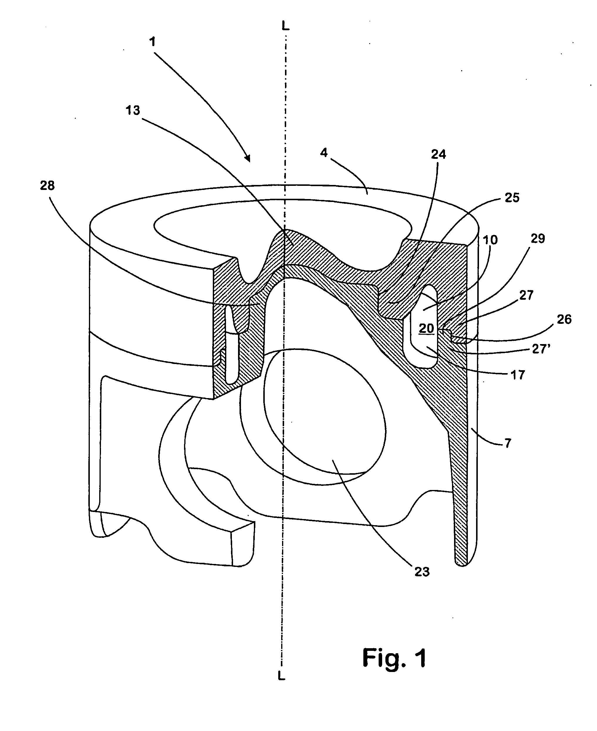
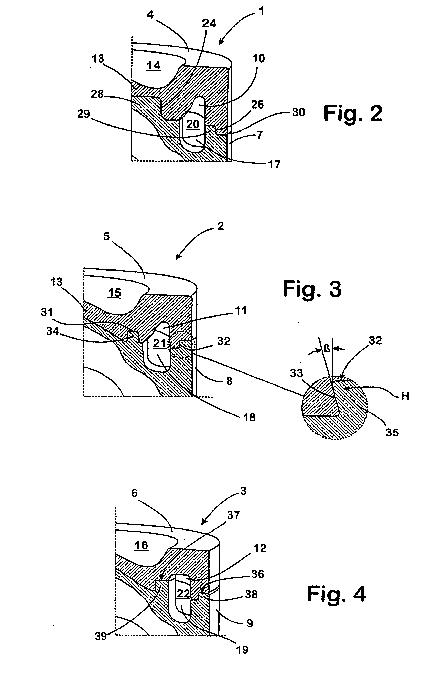
[0043]The pistons 1 to 3 shown in the figures are each of two-part construction, including a piston head part 4, 5, 6 and a piston skirt part 7, 8, 9. The piston head parts 4, 5, 6 are formed of a high- strength steel, such as stainless steel, whereas the piston skirt parts 7, 8, 9 can be made of a steel that is less strong but is highly deformable, or of a light material, such as aluminum.

[0044]The piston head parts 4, 5, 6 and the piston skirt parts 7, 8, 9 have each been pre-produced by forging. During the pre-production process, there is formed into the underside of the piston head parts 4, 5, 6, associated with the respective piston skirt part 7, 8, 9, an annular depression 10, 11, 12 in the form of a groove that encircles the central region 13 of the respective piston head part 4, 5, 6. A combustion cavity 14, 15, 16, which is configured in a manner known per se, is also formed at the free upper side of the piston head parts 4, 5, 6.

[0045]In the upper side of the respective pi...


PUM

PropertyMeasurementUnit
temperatureaaaaaaaaaa
shapeaaaaaaaaaa

Abstract

A piston for an internal-combustion engine is made up of a first part and a second part. One of the two parts forms the piston head and the other part forms the piston skirt. A cooling chamber, which is delimited by material of the first part and by material of the second part, is configured in the piston. The two parts are joined together positively and non-positively via a press fit formed by a projection of the second part, with the projection engaging with a recess in the first part.

Description

BACKGROUND AND SUMMARY OF THE INVENTION[0001]This application is a national stage of PCT International Application No. PCT / IB2008 / 002190, filed Aug. 22, 2008, which claims priority under 35 U.S.C. §119 to European Patent Application No. 07114934.8, filed Aug. 24, 2007, the entire disclosure of which is herein expressly incorporated by reference.[0002]The present invention relates to a piston for an internal-combustion engine. The piston has a cooling chamber, and is made up of two pre-produced parts. The invention also provides a method for manufacturing a piston of this type.[0003]Pistons for internal-combustion engines are conventionally manufactured by casting or forging. Production by casting has the advantage of allowing the manufacture of light pistons of complex shape. However, considerable production costs have to be allowed for. This is especially the case if steel is to be used as the material for the manufacture of particularly high-strength pistons.[0004]Depending on the...

Claims


Application Information

Patent Timeline
Patent Type & Authority Applications(United States)
IPC IPC(8): F16J1/00B23P11/02
CPCF02F3/003Y10T29/49865F02F2200/04F02F3/22
Inventor DE OLIVEIRA, MAURO APARECIDO FERREIRAFURQUIM, HERALDO CARLOSLOPES, JOAO LESTER GARCIA
Owner THYSSENKRUPP METALURGICA CAMPO LIMPO
Why Eureka
Try Eureka