Exhaust gas recirculation device of engine

a technology of exhaust gas recirculation and engine, which is applied in the direction of combustion-air/fuel-air treatment, electric control, instruments, etc., can solve the problems of restricted low pressure and temperature of the exhaust gas introduced into the intake passage via the downstream exhaust gas recirculation passage, and the restriction of nitrogen oxide along with the combustion of fuel in the combustion chamber. , to achieve the effect of reducing the temperature of the flam

Inactive Publication Date: 2011-06-30
TOYOTA JIDOSHA KK
View PDF15 Cites 8 Cited by
  • Summary
  • Abstract
  • Description
  • Claims
  • Application Information

AI Technical Summary

Benefits of technology

[0019]Further, according to the exhaust gas recirculation device of the engine of the seventh invention of this application, in any of the fifth and sixth inventions, when the temperature of the flame on the combustion of the fuel in the combustion chamber is higher than the allowable upper limit flame temperature, the reference exhaust gas recirculation ratio corrected such that the amount of the exhaust gas introduced into the intake passage via the first exhaust gas recirculation passage becomes zero, is set as the target exhaust gas recirculation ratio. According to this invention, compared with the case that the amount of the exhaust gas introduced into the intake passage via the first exhaust gas recirculation passage is not set to zero, the reference exhaust gas recirculation ratio can be corrected such that the amount of the exhaust gas introduced into the intake passage via the second exhaust gas recirculation passage becomes large. That is, in the case that the concentration of the oxygen in the gas introduced into the combustion chamber should be decreased when the temperature of the flame is higher than the allowable upper limit flame temperature, if the amount of the exhaust gas introduced into the intake passage via the second exhaust gas recirculation passage can be increased as possible, the temperature of the flame can be quickly decreased as possible. On the other hand, when the amount of the exhaust gas in the gas introduced into the combustion chamber excessively increases, resulting from the increase of the amount of the exhaust gas introduced into the intake passage via the second exhaust gas recirculation passage, the combustion of the fuel in the combustion chamber may be affected. However, according to this invention, since the amount of the exhaust gas introduced into the intake passage via the first exhaust gas recirculation passage is set to zero, the degree of the freedom of the correction of the reference exhaust gas recirculation ratio such that the amount of the exhaust gas introduced into the intake passage via the second exhaust gas recirculation passage is large, becomes large, without affecting the combustion of the fuel in the combustion chamber.

Problems solved by technology

Accordingly, the production of nitrogen oxide along with the combustion of the fuel in the combustion chamber is restricted.
The specification of the above-mentioned US patent Publication does not clearly disclose a difference in the property between the exhaust gas introduced into the intake passage via the upstream exhaust gas recirculation passage and the exhaust gas introduced into the intake passage via the downstream exhaust gas recirculation passage, however, generally, a pressure and a temperature of the exhaust gas introduced into the intake passage via the upstream exhaust gas recirculation passage are relatively high, while a pressure and a temperature of the exhaust gas introduced into the intake passage via the downstream exhaust gas recirculation passage are relatively low.
As explained above, when the temperature of the combustion of the fuel in the combustion chamber becomes low, the production of the nitrogen oxide along with the combustion of the fuel in the combustion chamber is restricted.

Method used


Image

  • Exhaust gas recirculation device of engine
  • Exhaust gas recirculation device of engine
  • Exhaust gas recirculation device of engine

Examples


first embodiment

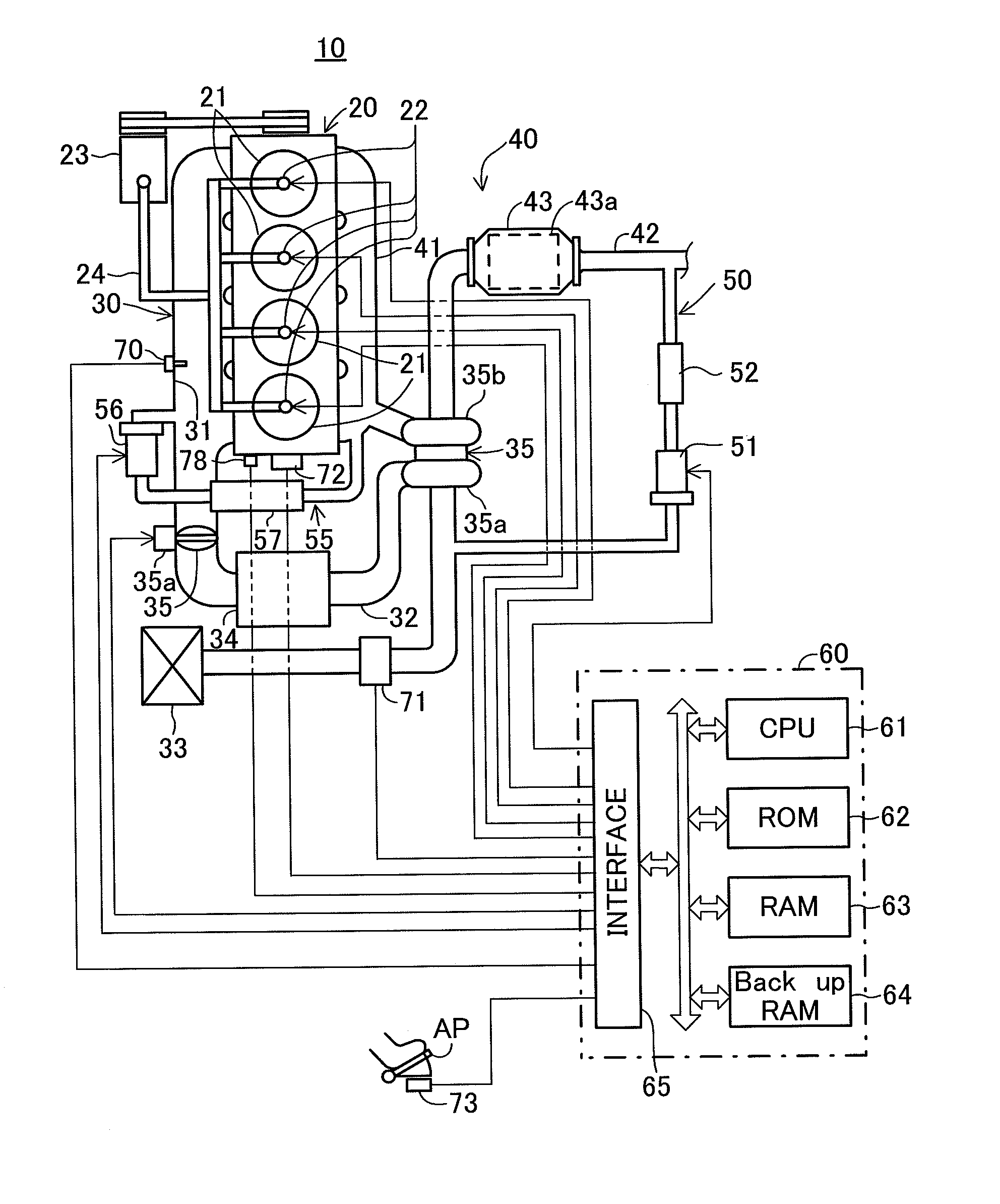
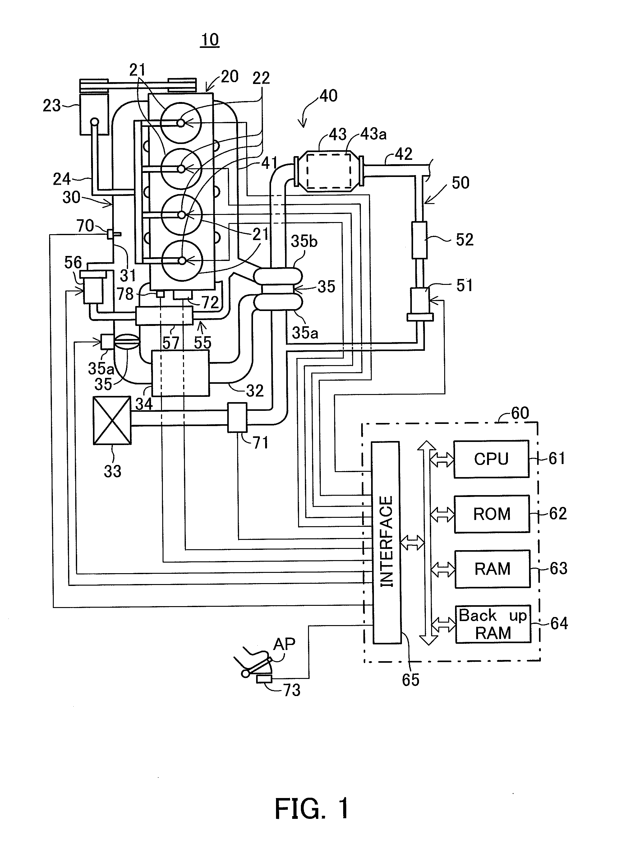
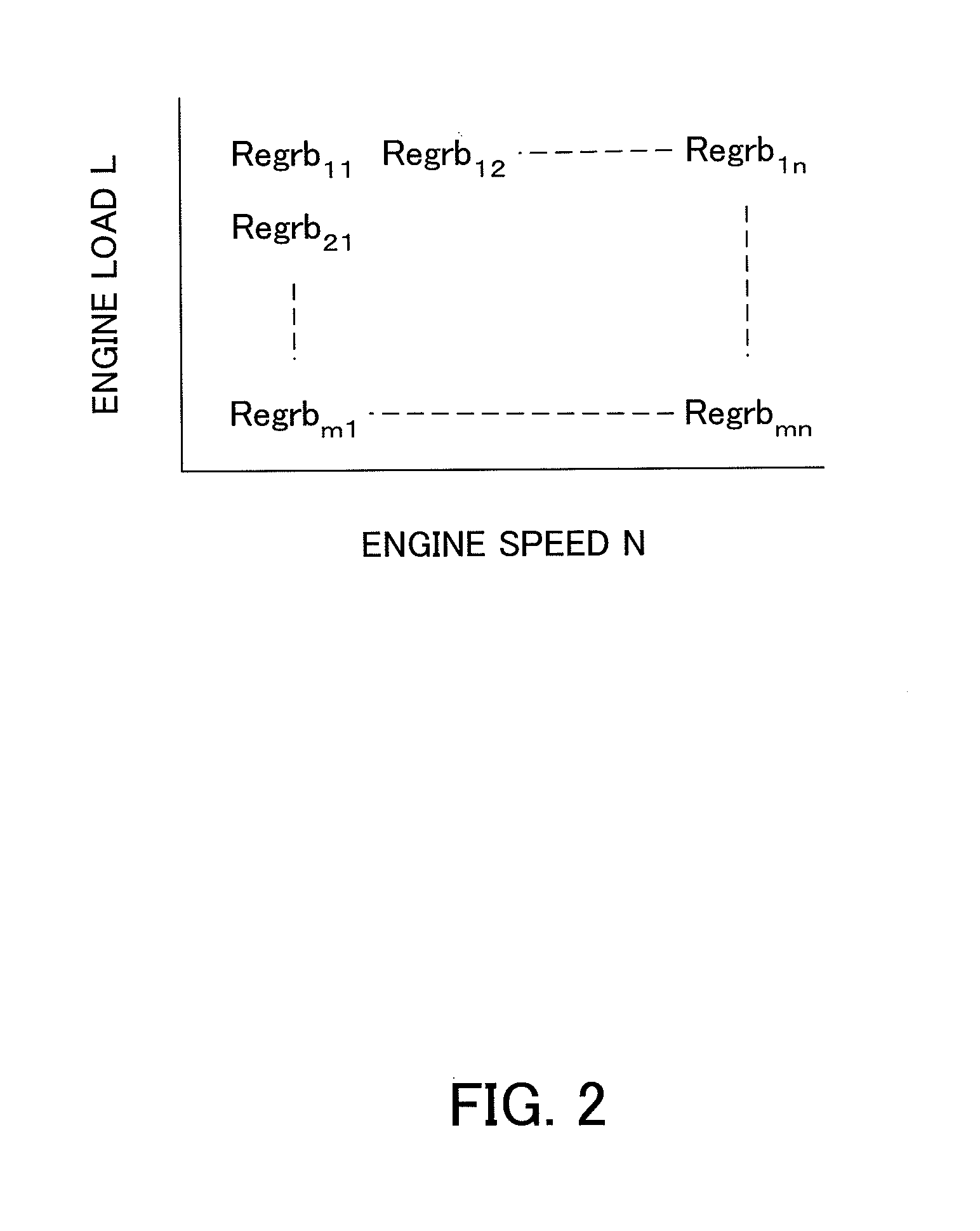
[0039]That is, in the first embodiment, most appropriate EGR ratios depending on the engine speed and the engine load (the detail of the most appropriate EGR ratio will be explained later) are previously obtained by an experiment, etc., and the EGR ratios are memorized in the ECU 60 as reference EGR ratios Regrb in the form of a map as a function of the engine speed N and the engine load L as shown in FIG. 2. During the operation of the engine, a reference EGR ratio Regrb is read from the map, depending on the engine speed N and the engine load L, and the reference EGR ratio is set as a target EGR ratio. The amount of the exhaust gas introduced into the intake passage 30 from the exhaust passage 40 via the first EGR passage 50 or the second EGR passage 55 is controlled by the first EGR control valve 51 or the second EGR control valve 56 such that an amount of the exhaust gas which can accomplish the target EGR ratio is introduced into the intake passage 30 from the exhaust passage 4...

second embodiment

[0074]It should be noted that in the second embodiment, the target EGR ratio may be set to an EGR ratio larger than the reference EGR ratio by a constant value, independently of the difference between the maximum flame temperature and the allowable upper limit flame temperature, i.e. the flame temperature difference or the target EGR ratio may be set to an EGR ratio larger than the reference EGR ratio, depending on the flame temperature difference. For example, in the case that the target EGR ratio is set to an EGR ratio larger than the reference EGR ratio, depending on the flame temperature difference, the target EGR ratio may be set to an EGR ratio which progressively increases as the flame temperature difference becomes large or the target EGR ratio may be set to an EGR ratio which continuously increases as the flame temperature difference becomes large. In this case, the concentration of the oxygen in the gas introduced into the combustion chamber is decreased as the maximum fla...

third embodiment

[0078]That is, in this embodiment (hereinafter, referred to as “third embodiment”), when the maximum flame temperature is higher than the allowable upper limit flame temperature, a reference EGR ratio Regrb is read from the map shown in FIG. 2, depending on the engine speed N and the engine load L and a reference EGR gas ratio Rb is read from the map shown in FIG. 3, depending on the engine speed N and the engine load L. Then, the first and second EGR gas amounts which can accomplish the reference EGR ratio and the reference EGR gas ratio, are calculated as reference first and second EGR gas amounts, respectively. Then, the reference first EGR gas amount calculated as explained above is set as the target first EGR gas amount. On the other hand, the target second EGR gas amount is set as follows.

[0079]That is, in the third embodiment, a reference oxygen concentration Cob is read from the map shown in FIG. 4, depending on the engine speed N and the engine load L and the reference oxyg...


PUM


Abstract

An exhaust gas recirculation device of an engine (10) of the invention comprises a first exhaust gas recirculation passage (50) for connecting an exhaust passage (40) and an intake passage (30) to each other and introducing into the intake passage an exhaust gas discharged from a combustion chamber (21) to the exhaust passage, and a second exhaust gas recirculation passage (55) for connecting the exhaust passage upstream of a part of the exhaust passage connected to the first exhaust gas recirculation passage and the intake passage downstream of a part of the intake passage connected to the first exhaust gas recirculation passage to each other and introducing into the intake passage the exhaust gas discharged from the combustion chamber to the exhaust passage. The amount of the exhaust gas introduced into the intake passage via the first exhaust gas recirculation passage is controlled to a first target exhaust gas recirculation amount and the amount of the exhaust gas introduced into the intake passage via the second exhaust gas recirculation passage is controlled to a second target exhaust gas recirculation amount. When a temperature of the flame on the combustion of a fuel is lower than or equal to an allowable upper limit flame temperature, a first reference exhaust gas recirculation amount set depending on the operation condition of the engine, is set as the first target exhaust gas recirculation amount and a second reference exhaust gas recirculation amount set depending on the operation condition of the engine, is set as the second target exhaust gas recirculation amount. When the temperature of the flame on the combustion of the fuel is higher than the allowable upper limit flame temperature, one of the first reference exhaust gas recirculation gas amount and an amount smaller than the first reference exhaust gas recirculation gas amount is set as the first target exhaust gas recirculation amount and an amount larger than the reference second exhaust gas recirculation amount is set as the second target exhaust gas recirculation amount.

Description

TECHNICAL FIELD[0001]The present invention relates to an exhaust gas recirculation device of an engine.BACKGROUND ART[0002]An exhaust gas recirculation device for recirculating an exhaust gas into combustion chambers by introducing into an intake passage of an engine, an exhaust gas discharged from the combustion chambers of the engine to an exhaust passage, is disclosed in the specification of US Patent Publication No. 2009 / 013253. Much inert gas such as carbon dioxide is included in the exhaust gas, and therefore a temperature of combustion of fuel in the combustion chamber is decreased by recirculating the exhaust gas into the combustion chamber. Accordingly, the production of nitrogen oxide along with the combustion of the fuel in the combustion chamber is restricted.[0003]The specification of the above-mentioned US patent Publication discloses the exhaust gas recirculation device comprising an exhaust gas recirculation passage (hereinafter, this passage is referred to as “upstr...

Claims


Application Information

Patent Timeline
Patent Type & Authority Applications(United States)
IPC IPC(8): F02M25/07
CPCF02D35/026F02D41/0065F02D2250/36Y02T10/47F02M25/0709F02M35/1038F02M37/06F02M25/0707F02M26/05F02M26/06Y02T10/40
Inventor ONISHI, TOMOMIODA, TOMIHISAKAWAGUGUCHI, BUNGOSATOU, MASAAKIKOBAYAKAWA, SATOSHISHIRASAWA, TAKERU
Owner TOYOTA JIDOSHA KK
Why Eureka
Try Eureka