Residual stress improving method for pipe

a stress improvement and pipe technology, applied in the field of resistive stress improvement methods of pipes, can solve the problems of stress corrosion cracking, the residual stress of pipes may not be sufficiently improved, so as to improve the residual stress condition, prevent stress corrosion cracking, and improve the effect of residual stress

Inactive Publication Date: 2011-06-30
HITACHI LTD
View PDF2 Cites 9 Cited by
  • Summary
  • Abstract
  • Description
  • Claims
  • Application Information

AI Technical Summary

Benefits of technology

[0021]According to an aspect of the present invention, large compressive residual stress can be imparted to the inner surface of the stress improving region of the pipe, the residual stress condition can be improved, and stress corrosion cracking can be prevented by applying the axial load of stress with which the axial strain of the outer surface of the pipe is 0% or above and which is yield stress of the pipe or below in plastic deformation of the pipe when the internal pressure of the pipe is raised and the axial load is applied to the stress improving region where residual stress of the pipe is to be improved.

Problems solved by technology

With respect to a pipe using stainless steel, nickel alloy and the like, when it is exposed to high temperature pure water for a long time while being applied with tensile residual stress at the welding section of the pipe, stress corrosion cracking may possibly occur.
Therefore, according to the diameter and thickness of the pipe, the residual stress of the pipe may not be sufficiently improved to the degree stress corrosion cracking is prevented.
In this case, according to the magnitude of the tensile load applied, the residual stress of the pipe may not be sufficiently improved to the degree the stress corrosion cracking is prevented.

Method used


Image

  • Residual stress improving method for pipe
  • Residual stress improving method for pipe
  • Residual stress improving method for pipe

Examples


Embodiment Construction

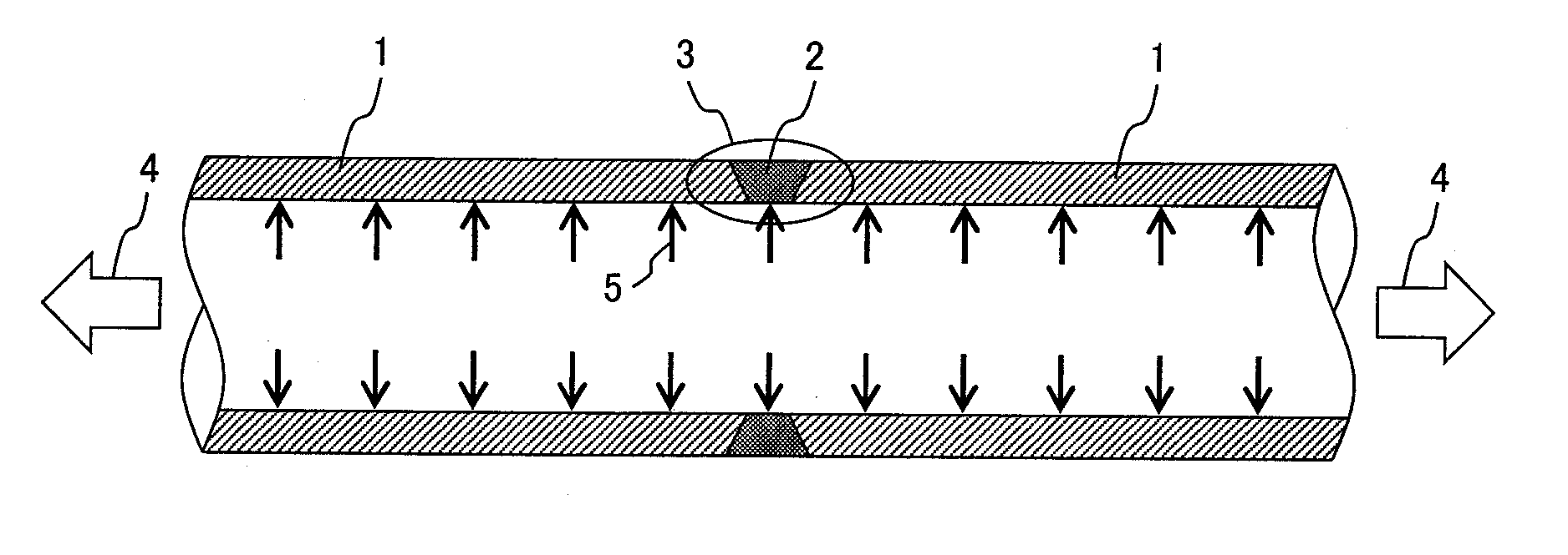
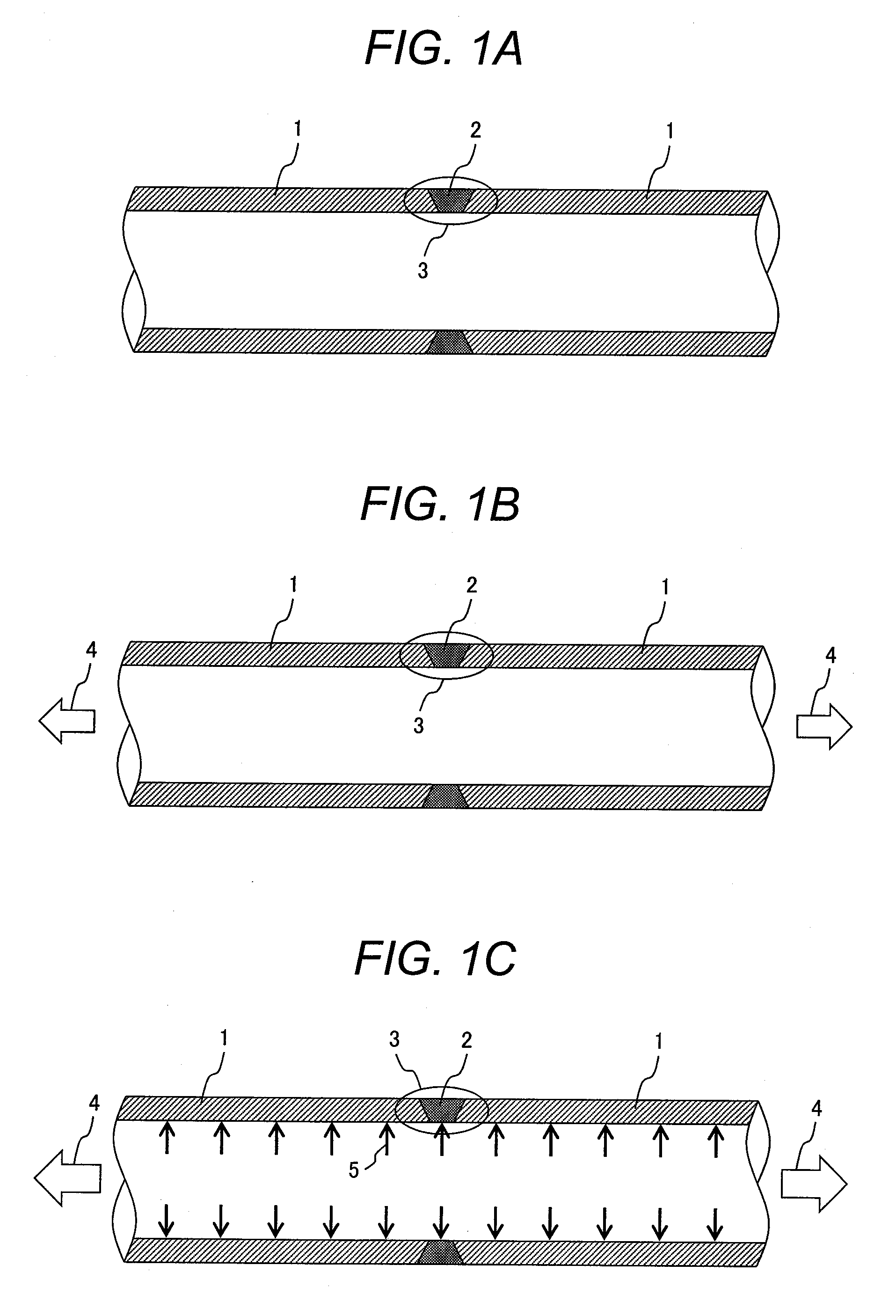
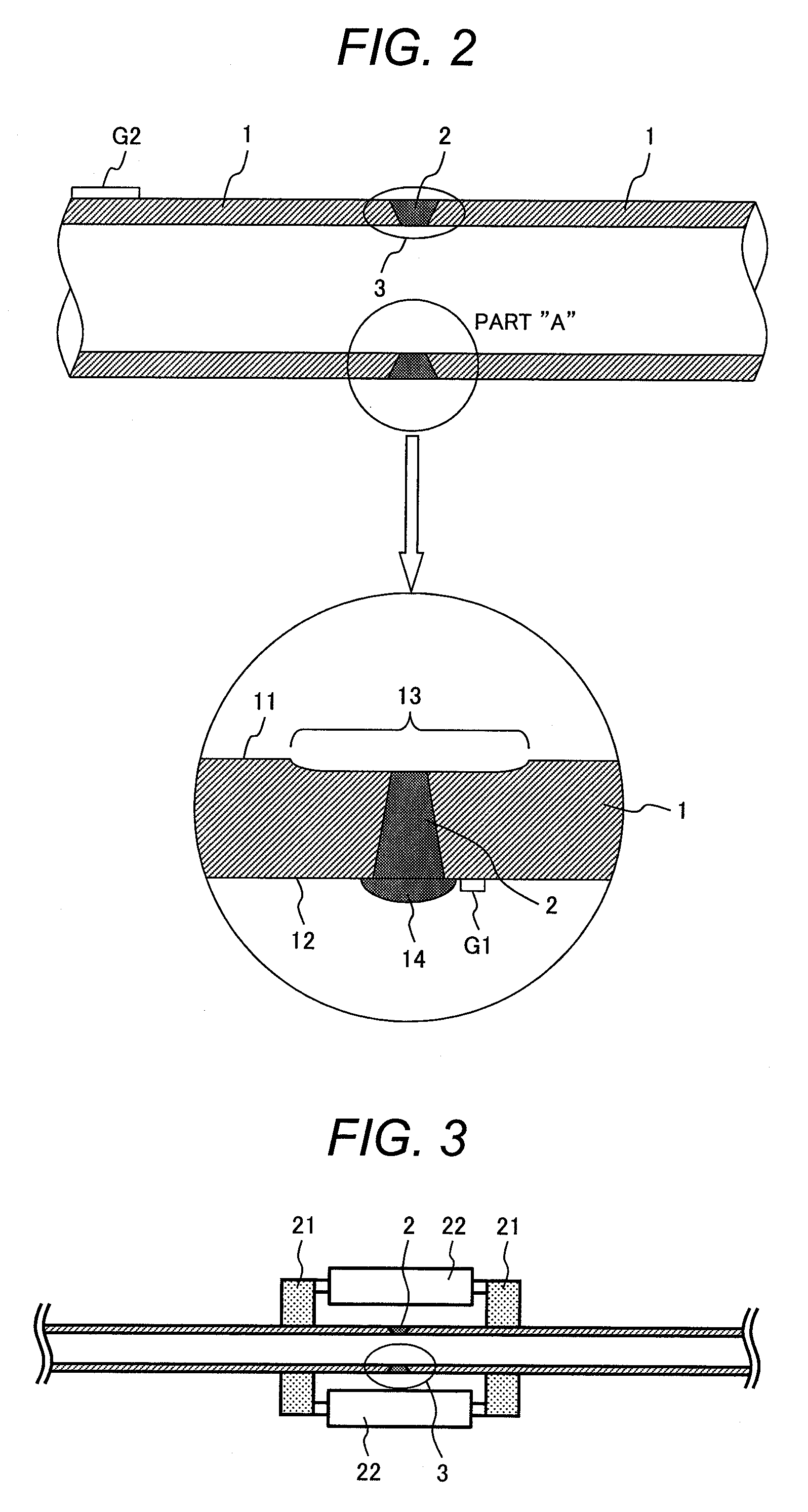
[0038]The present inventors investigated a method capable of imparting larger compressive residual stress on the inner surface of the welding section and the vicinity of the welding section of a pipe. As a result, the present inventors have newly found out that it is preferable to impart large compressive residual stress on the inner surface of a stress improving region of the pipe where the residual stress of the pipe is to be improved by raising the axial load and the internal pressure of the pipe to perform plastic deformation with respect to the stress improving region and applying an axial load with which the axial strain of the outer surface of the pipe is 0% or above and the stress is the yield stress of the pipe or below in plastic deformation.

[0039]Thus, probability of occurrence of stress corrosion crack in a pipe can be further lowered by imparting larger compressive residual stress on the inner surface of the stress improving region of the pipe and reducing the tensile r...


PUM

PropertyMeasurementUnit
yield stressaaaaaaaaaa
Young's modulusaaaaaaaaaa
thicknessaaaaaaaaaa

Abstract

It is an object to provide a residual stress improving method for a pipe by imparting larger compressive residual stress on the pipe to sufficiently reduce tensile residual stress in order to prevent the stress corrosion cracking. With respect to a stress improving region where the residual stress of a pipe is to be improved, a load in the axial direction of the pipe is made such stress making axial strain of the outer surface of the pipe 0% or above and being yield stress of the pipe or below, and internal pressure of the pipe is raised. The pipe is plastically deformed and is expanded in the radial direction by the internal pressure. After the internal pressure is raised to the degree the pipe is plastically deformed, the internal pressure and the axial load are removed, and thereby compressive residual stress is imparted to a welding section and a heat affected zone which are the stress improving region of the inner surface of the pipe.

Description

CLAIM OF PRIORITY[0001]The present application claims priority from Japanese patent application serial No. 2009-294016 filed on Dec. 25, 2009, the content of which is hereby incorporated by reference into this applicationBACKGROUND OF THE INVENTION[0002]1. Field of the Invention[0003]The present invention relates to a residual stress improving method for a pipe, and relates specifically to a residual stress improving method for a pipe suitable in improving the residual stress in the vicinity of a welding section of a pipe.[0004]2. Description of the Related Arts[0005]With respect to a pipe used for a power plant, the residual stress occurs in the vicinity of the welding section when welding is performed. Also, a stainless steel pipe or a nickel alloy pipe is commonly used for a pipe for high temperature water considering corrosion resistance. With respect to a pipe using stainless steel, nickel alloy and the like, when it is exposed to high temperature pure water for a long time whi...

Claims


Application Information

Patent Timeline
Patent Type & Authority Applications(United States)
IPC IPC(8): C21D8/10
CPCB21C37/0811B21C37/16B23K31/00C21D9/50C21D7/12C21D8/105B23K2201/06B23K2101/06
Inventor IWAMATSU, FUMINORI
Owner HITACHI LTD
Why Eureka
Try Eureka