Motor driving device, electric power steering device using the same and method for detecting failure in the same

Active Publication Date: 2011-06-30
DENSO CORP
View PDF5 Cites 61 Cited by
  • Summary
  • Abstract
  • Description
  • Claims
  • Application Information

AI Technical Summary

Benefits of technology

[0007]According to one aspect of the present invention, a motor driving device comprises a motor including a plurality of winding sets having windings corresponding to a plurality of phases. The motor driving device further comprises an inverter unit provided for each of the winding sets and configured to supply a current to the windings, the inverter unit including a plurality of switching elements including switching element pairs respectively corresponding to the phases of the windings, each of the switching element pairs including a high potential-side switching element on a high potential side and a low potential-side switching element on a low potential side. The motor driving device further comprises a switching unit configured to switch each of the switching elements between on and off. The motor driving device further comprises a voltage application unit configured to apply a voltage to the windings without passing through the inverter unit. The motor driving device further comprises a power voltage detection unit configured to detect a power voltage between the inverter unit and a power supply. The motor driving device further comprises a terminal voltage detection unit configured to detect a terminal voltage at a contact between each of the switching elements and corresponding one of the windings. The motor driving device further comprises a control unit including a rotation control unit, a first failure detection unit, and a second failure detection unit. The rotation control unit is configured to control the switching unit to switch each of the switching elements between on and off to control rotation of the motor. The first failure detection unit is configured to detect a short circuit failure in the switching elements based on the terminal voltage and the power voltage before the rotation control unit starts control of the rotation of the motor. The second failure detection unit is configured such that, before the rotation control unit starts control of the rotation of the motor and when the first failure detection unit does not detect a failure in the switching elements and in a condition where the switching unit is caused to switch at least one of the high potential-side switching element and the low potential-side switching element on and subsequently switch all the switching elements off, the second failure detection unit determines whether the switching unit is incapable of rendering the switching element non-conductive to detect a short circuit failure in the switching unit based on the terminal voltage and the power voltage.
[0008]According to another aspect of the present invention, a method for detecting failure in a motor driving device, the motor driving device including: a motor including a plurality of winding sets having windings corresponding to a plurality of phases; an inverter unit provided for each of the winding sets and configured to supply a current to the windings, the inverter unit including a plurality of switching elements including switching element pairs respectively corresponding to the phases of the windings, each of the switching element pairs including a high potential-side switching element on a high potential side and a low potential-side switching element on a low potential side; and a switching unit configured to switch each of the switching elements between on and off, the method comprises detecting a power voltage between the inverter unit and a power supply. The method further comprises detecting a terminal voltage at a contact between each of the switching elements and corresponding one of the windings; applying a voltage to the windings without passing through the inverter unit to detect a short circuit failure in the switching elements based on the terminal voltage and the power voltage before rotation of the motor. The method further comprises causing, before rotation of the motor and when the short circuit failure in the switching elements is not detected, the switching unit to switch on at least one of the high potential-side switching element and the low potential-side switching element and subsequently switch all the switching elements off and determining whether the switching unit is incapable of rendering the switching element non-conductive to detect a short circuit failure in the switching unit based on the terminal voltage and the power voltage.

Problems solved by technology

However, when the above-mentioned so-called PWM driving is carried out in inverter failure detection, a problem may arise.

Method used


Image

  • Motor driving device, electric power steering device using the same and method for detecting failure in the same
  • Motor driving device, electric power steering device using the same and method for detecting failure in the same
  • Motor driving device, electric power steering device using the same and method for detecting failure in the same

Examples


first embodiment

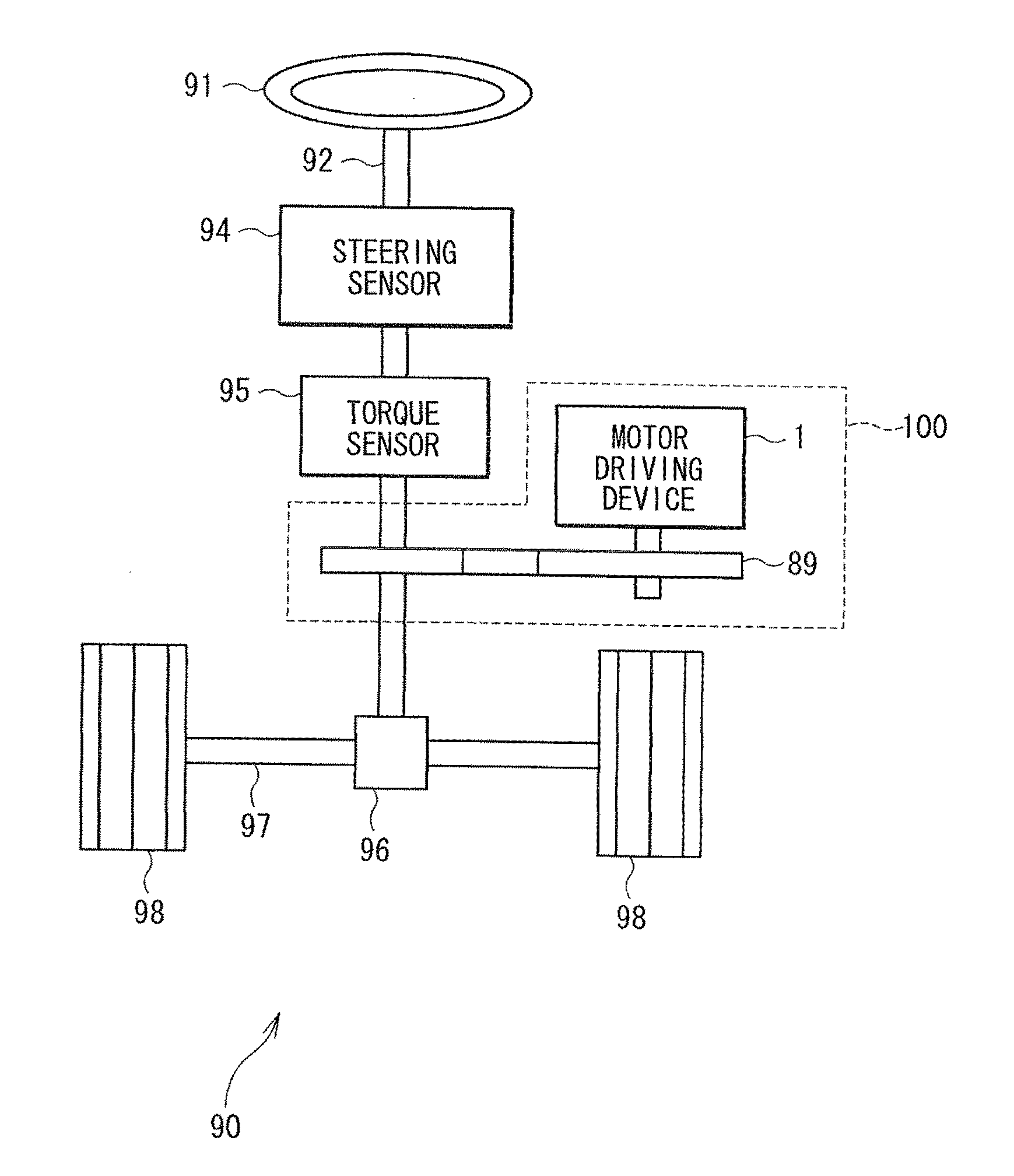
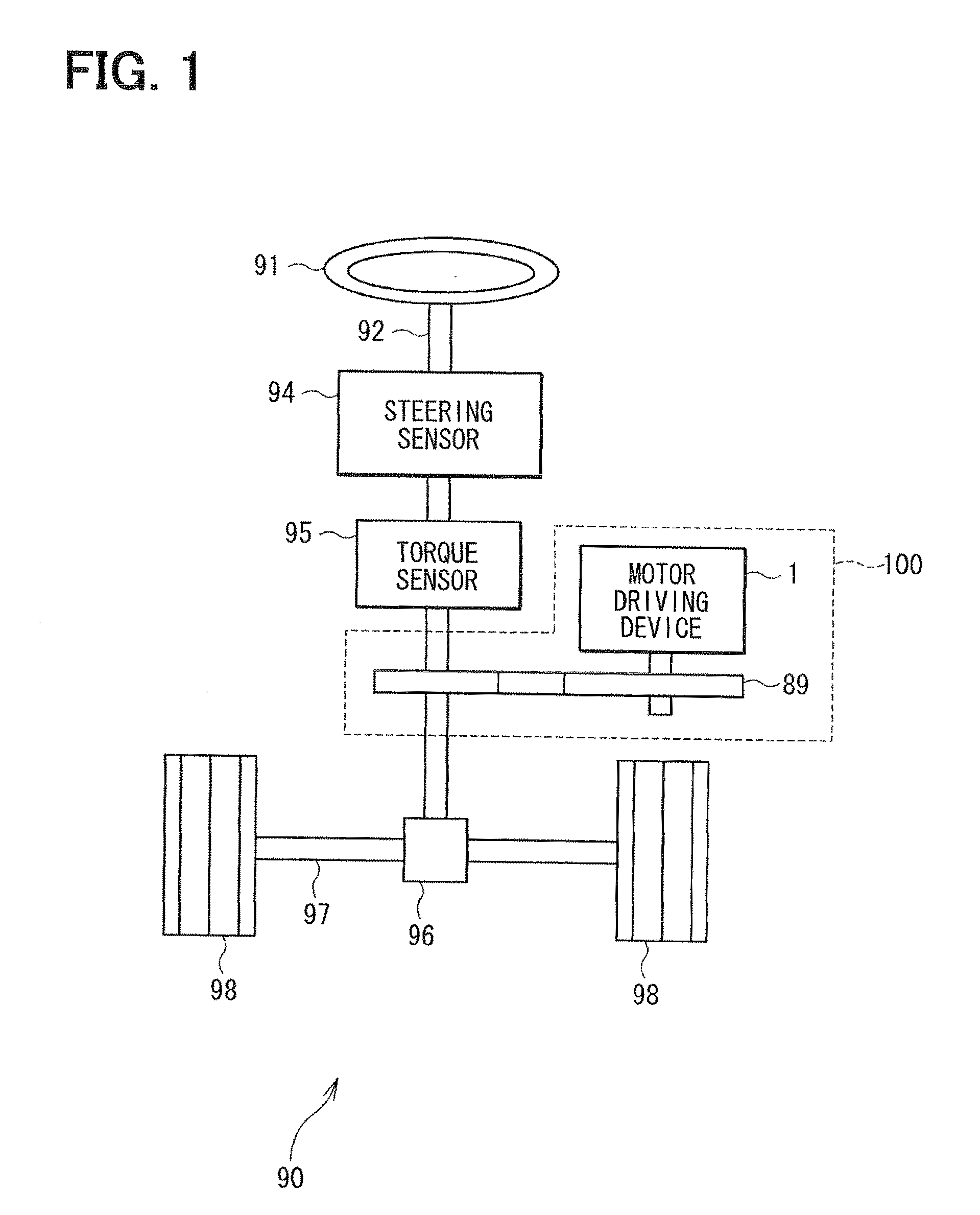
[0026]FIG. 1 illustrates the overall configuration of a steering system equipped with an electric power steering device in the first embodiment of the invention. The steering shaft 92 connected to the steering wheel 91 of the electric power steering device 100 provided in the steering system 90 is provided with a steering sensor 94 and a torque sensor 95. The steering sensor 94 detects the rotation angle of the steering shaft 92. The torque sensor 95 detects steering wheel torque applied to the steering wheel. The tip of the steering shaft 92 is coupled to a rack shaft 97 through a gear 96. A pair of tires (wheels) 98 is coupled to both ends of the rack shaft 97 through a tie rod and the like. The rotational motion of the steering shaft 92 is converted into the linear motion of the rack shaft 97 by the gear 96 and the left and right tires 98 are steered by an angle equivalent to the linear motion displacement of the rack shaft 97.

[0027]The electric power steering device 100 includes...

second embodiment

[0109]The circuitry and the like of the electric power steering device 100 and the motor driving device 1 in the second embodiment of the motor driving device are the same as those in the first embodiment and the description thereof will be omitted. Here, description will be given only to failure detection processing. As in the first embodiment, the failure detection processing in the first inverter unit 20 and the failure detection processing in the second inverter unit 30 are identical with each other; therefore, the failure detection processing in the first inverter unit 20 will be described here. The failure detection processing in the first inverter unit 20 and the failure detection processing in the second inverter unit 30 can be simultaneously carried out.

[0110]Description will be given to the main flow of the failure detection processing illustrated in FIG. 9. The failure detection processing illustrated in FIG. 9 is carried out when the ignition switch 58 is turned on. At S...


PUM


Abstract

A voltage application unit applies voltage to windings of a motor without passing though an inverter unit. A first detection unit detects a short circuit failure in switching elements of the inverter unit based on a terminal voltage between each of the switching elements and a corresponding winding and a power voltage of a power supply. Before rotation of the motor, when no short circuit failure is detected and when a switching unit switches at least one of the high and low potential-side switching elements of the inverter unit on and subsequently switches all the switching elements off, a second failure detection unit determines whether the switching unit is incapable of rendering the switching element non-conductive based on the terminal voltage and the power voltage.

Description

CROSS REFERENCE TO RELATED APPLICATIONS[0001]This application is based on and incorporates herein by reference Japanese Patent Application No. 2009-292691 filed on Dec. 24, 2009.FIELD OF THE INVENTION[0002]The present invention relates to a motor driving device. The present invention further relates to an electric power steering device using the motor driving device. The present invention further relates to a method for detecting failure in the motor driving device.BACKGROUND OF THE INVENTION[0003]Motor driving devices that drive a motor by windings of multiple phases are conventionally known. In the electric power steering device disclosed in JPA-2009-6963, which corresponds to US 2010 / 0017063 A1, for example, a three-phase brushless motor is used and when any anomaly occurs in one phase, control is carried out to continue driving of the motor by the remaining two phases.[0004]In general, any failure is detected in switching elements, a pre-driver, and the like before starting driv...

Claims


Application Information

Patent Timeline
Patent Type & Authority Applications(United States)
IPC IPC(8): H02P6/12
CPCB62D5/0487G01R31/025H02P2207/05H02P29/021G01R31/42H02P29/0241G01R31/52
Inventor MUKAI, YASUHIKOURYU, NOBUHIKO
Owner DENSO CORP
Why Eureka
Try Eureka