
Computer system with overclocking function and method

a computer system and function technology, applied in the field of computer systems, can solve the problems of consuming too much power, and wasting too much time in rebooting the computer system, and achieve the effect of quick completion of the static overclocking process and maintaining the stability of the computer system

Active Publication Date: 2011-06-30
ASUSTEK COMPUTER INC
View PDF6 Cites 17 Cited by
  • Summary
  • Abstract
  • Description
  • Claims
  • Application Information

AI Technical Summary

Benefits of technology

The invention provides a computer system with an overclocking function and a method for controlling it. The method allows for quick and stable overclocking, and the computer system remains stable after the overclocking process. The invention also includes steps for setting an operating voltage and clock rate, controlling the computer system into a sleep mode, and resuming the computer system after a predetermined time. The method also allows for an adjusted operating voltage and clock rate to be set, and the computer system can be controlled to enter a sleep mode and resume after a predetermined time. The technical effects of the invention include quick and stable overclocking with a stable computer system, as well as improved performance and efficiency.

Problems solved by technology

However, it also consumes much power.
However, it consumes too much time in rebooting the computer system.
Thus, the problem occurred in the static overclocking process that wastes too much time can be solved.
However, the clock rate adjusted by the dynamic overclocking process is just an unstable clock rate, but not an optimum clock rate.
As a result, the temperature of the computer system is increased after a long time operation, the computer is unstable, and the system also may crash.
As stated above, the computer system must be rebooted in the conventional static overclocking process, and keeps the user waits for a long time.
Moreover, the conventional dynamic overclocking process may make the computer system unstable.

Method used


Image

  • Computer system with overclocking function and method
  • Computer system with overclocking function and method
  • Computer system with overclocking function and method

Examples


Embodiment Construction

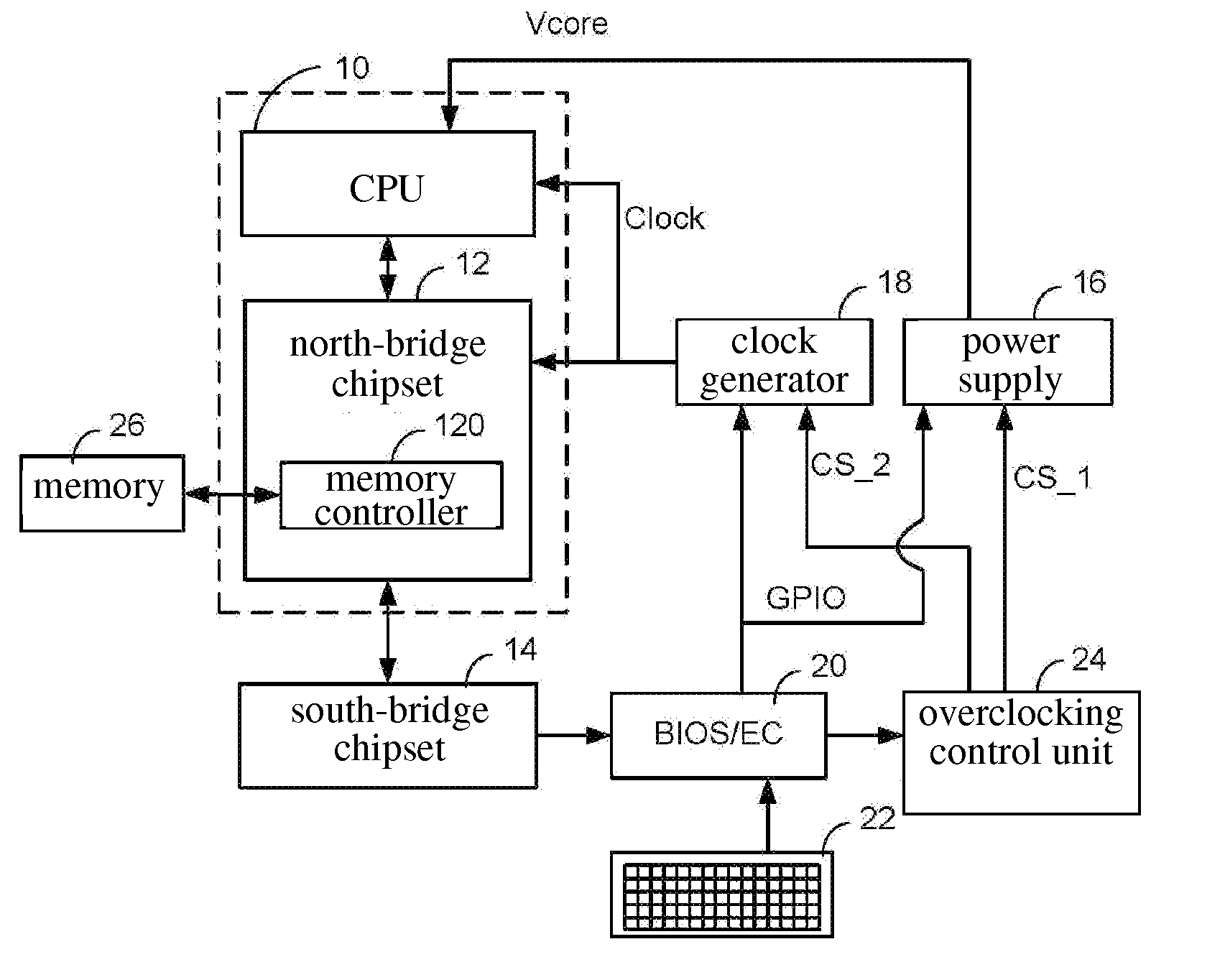
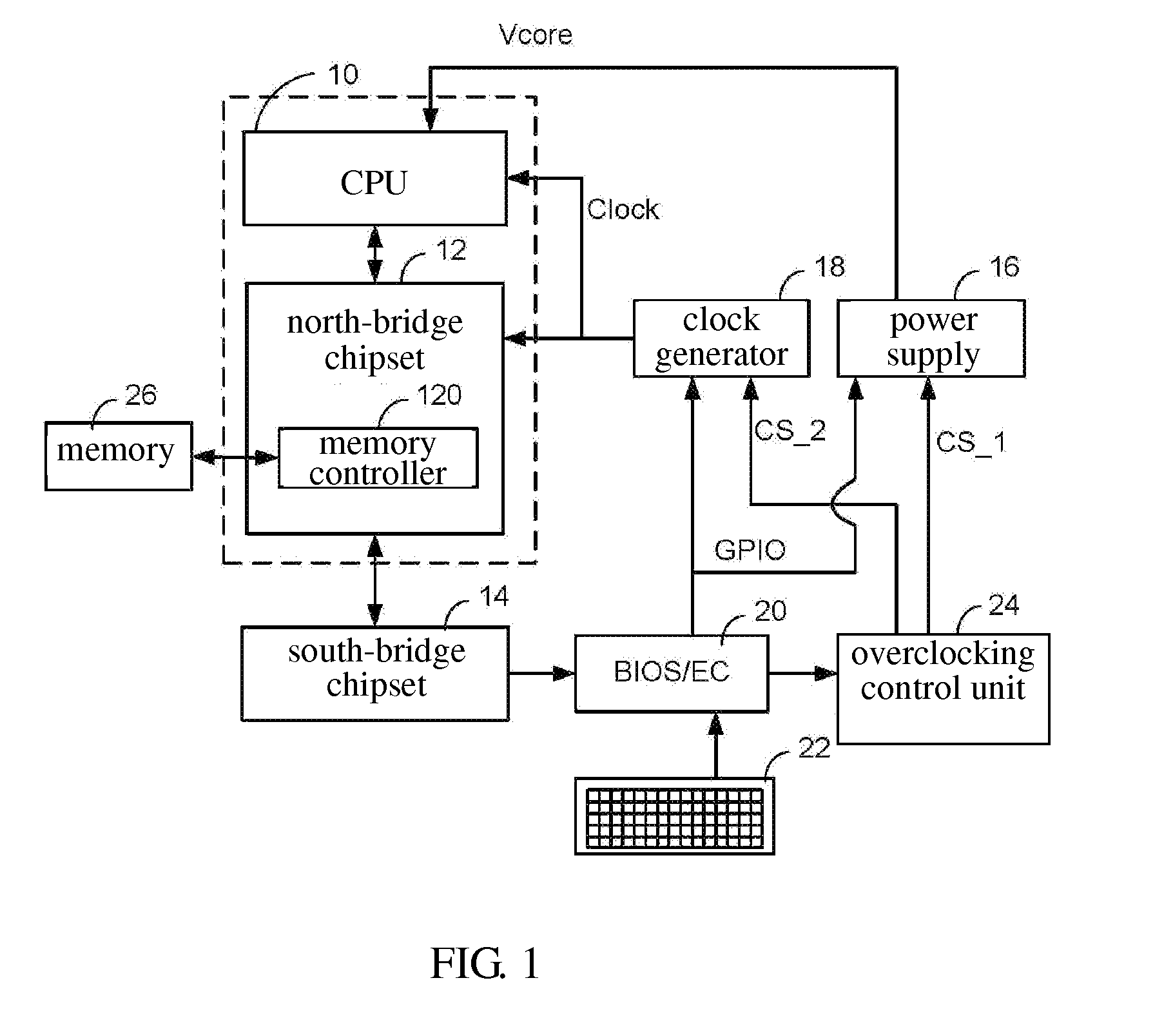
[0013]FIG. 1 is a diagram showing a computer system with the overclocking function in an embodiment. The computer system can adjust the operating voltage (Vcore) and the clock rate of a central processing unit (CPU) and a north bridge chipset. The computer system mainly includes a CPU 10, a north bridge chipset 12, a south-bridge chipset 14, a power supply 16, a clock generator 18, a basic input / output system and embedded controller (BIOS / EC) 20, a keyboard 22, an overclocking control unit 24 and a memory 26. The north bridge chipset 12 further includes a memory controller 120 for controlling data exchanging between the north bridge chipset 12 and the memory 26. The CPU 10 and the north bridge chipset 12 can be integrated to a single chip. The power supply 16 adjusts the operating voltage (Vcore) outputted to the CPU 10 according to a first control signal CS_1. The clock generator 18 adjusts the clock rate of the CPU 10 and the north bridge chipset 12 according to a second control s...


PUM


Abstract

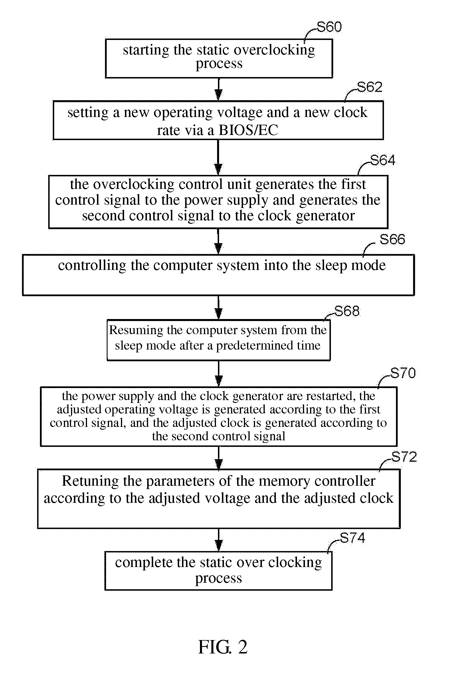
An overclocking method applied to a computer system includes the following steps: setting a first operating voltage and a first clock rate; generating a first control signal to a power supply and generating a second control signal to a clock generator according to the first operating voltage and the first clock rate, respectively; controlling the computer system into a sleep mode; resuming the computer system from the sleep mode after a predetermined time; restarting the power supply and the clock generator, and generating the first operating voltage by the power supply according to the first control signal and, generating the first clock rate by the clock generator according to the second control signal; and setting a parameter of a memory controller in a north bridge chip of the computer system via the first clock rate and the first operating voltage.

Description

FIELD OF THE INVENTION[0001]The invention relates to a computer system, more particularly, to a computer system with overclocking function.BACKGROUND OF THE INVENTION[0002]In general, the users can use a basic input / output system (BIOS) to control the operating voltage (CPU Vcore) or the clock rate of the computer system, which is so called a static overclocking process. Further, some of the manufacturer of the computer system provides a user interface (UI) for a user to control the operating voltage (Core) or the clock rate of the computer system, which is so called a dynamic overclocking process. Generally speaking, the whole efficiency of the computer system can be improved by increasing the operating voltage and the clock rate. However, it also consumes much power. On the contrary, the efficiency of the computer system is lowered by decreasing the operating voltage and the clock rate. However, it saves power. Thus, the users can control the computer system to keep the best effic...

Claims


Application Information

Patent Timeline
Patent Type & Authority Applications(United States)
IPC IPC(8): G06F1/32
CPCG06F1/08Y02B60/1217G06F1/3203Y02D10/00
Inventor HUANG, REN-JIUNLU, BEN-JEN
Owner ASUSTEK COMPUTER INC
Learn More