Positioning apparatus, exposure apparatus, and device manufacturing method

a technology of exposure apparatus and positioning position, which is applied in the direction of photomechanical apparatus, instruments, printing, etc., can solve the problems of affecting the deformation of the actuator arrangement between the design value and the real apparatus, so as to reduce the effect of the elastic vibration mod

Inactive Publication Date: 2011-07-07
CANON KK
View PDF3 Cites 21 Cited by
  • Summary
  • Abstract
  • Description
  • Claims
  • Application Information

AI Technical Summary

Benefits of technology

[0009]The present invention is directed to reducing the effect of the elastic vibration mode in a real apparatus e

Problems solved by technology

Although an actuator having a large thrust is used to meet the above-mentioned requirements, the use of such an actuator may increase heat generation therein, possibly resulting in degradation in positioning accuracy.
However, since weight reduction of the stages decreases an eigenvalue of the elastic vibration mode of the stage structure, gain and phase margins of the position control system decrease and oscillation of the elastic vibration mode becomes likely to occur, thus making it difficult to improve the control band.
Although the deformation shape of the elastic vibration mode can be obtained by using finite element method (FEM) simulation, the deformation shape obtained by the simulation does not completely agree with the deformation shape measured on a real apparatus, resulting in an error.
There is also an error in actuator arrangement between design values and the real apparatus because of a manufacture error.
Therefore, even when the

Method used


Image

  • Positioning apparatus, exposure apparatus, and device manufacturing method
  • Positioning apparatus, exposure apparatus, and device manufacturing method
  • Positioning apparatus, exposure apparatus, and device manufacturing method

Examples


Embodiment Construction

[0023]Various exemplary embodiments, features, and aspects of the invention will be described in detail below with reference to the drawings.

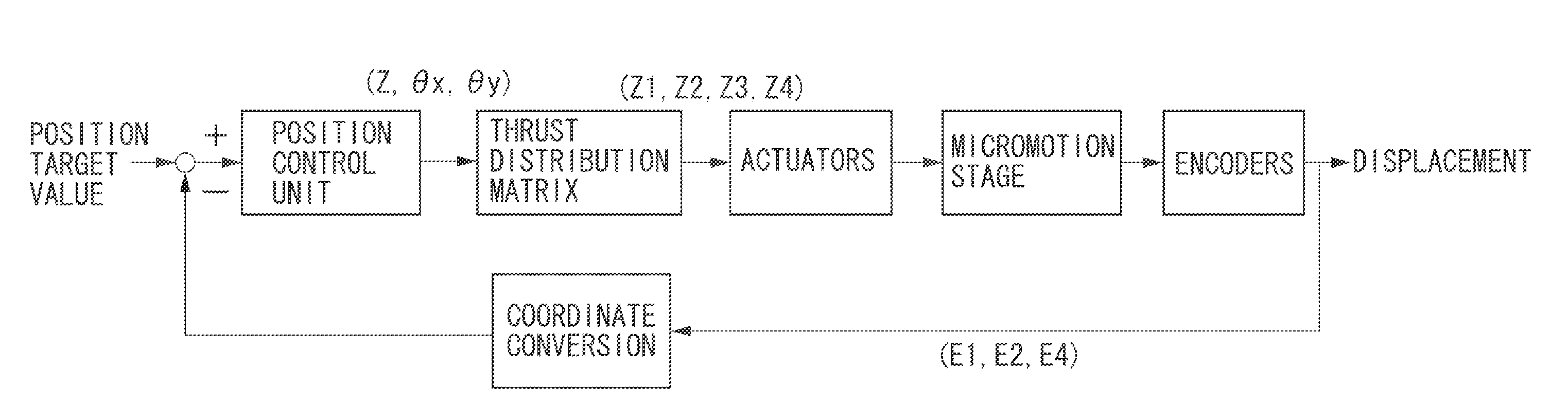
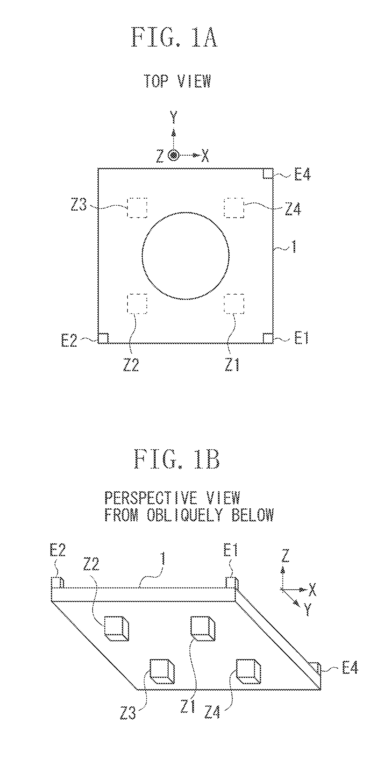
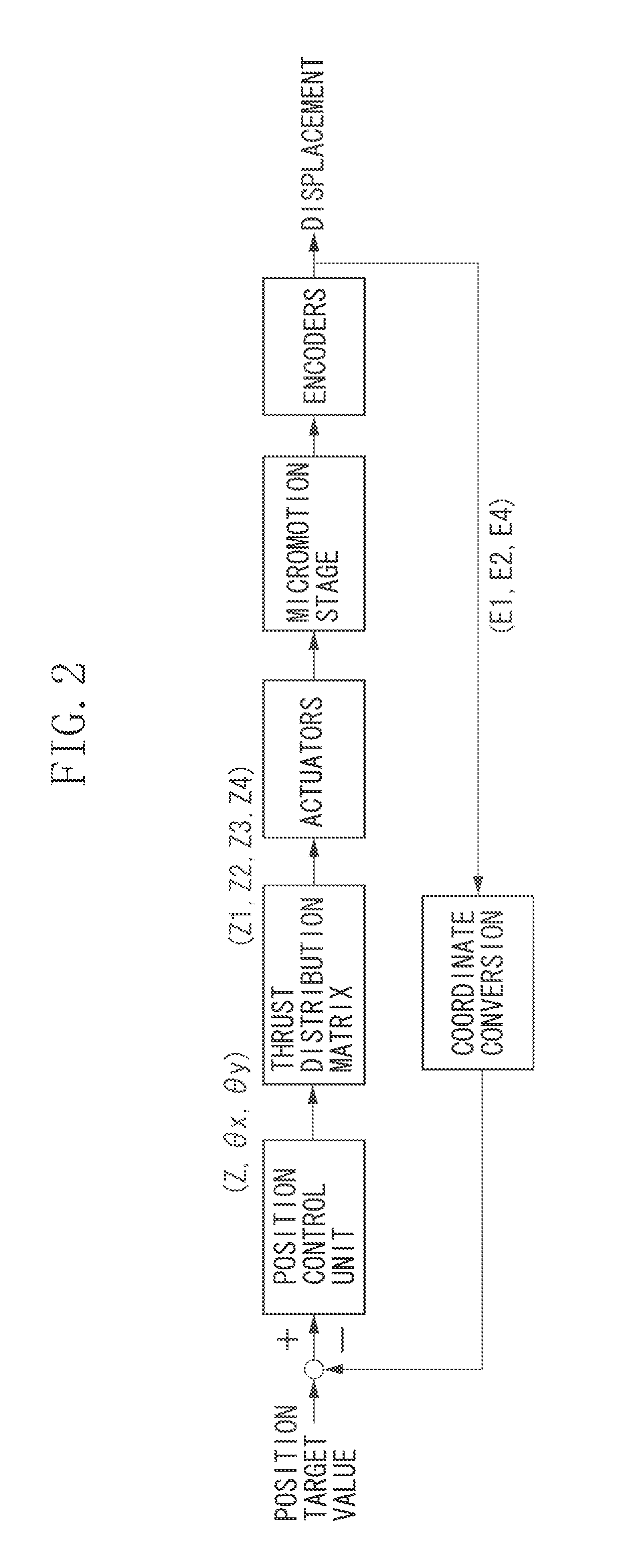
[0024]FIGS. 1A and 1B illustrate an overall configuration of a stage according to a first exemplary embodiment. FIG. 2 is a block diagram of a stage control system. Although this block diagram illustrates only the Z, θx, and θy axes, the control system of a real apparatus also includes the X, Y, and θz axes. θx, θy, and θz denote rotation around the X, Y, and Z axes, respectively.

[0025]A stage tabletop 1 serves as a stage (a positioning apparatus) on which a workpiece is placed. The stage tabletop 1 is a flat plate having an approximate square shape and a hollow structure for weight reduction. The stage tabletop 1 is composed of, for example, an upper and lower plates connected with ribs or beams. To measure the stage position, the stage is provided with encoders E1, E2, and E4 for measuring the displacement in the Z-axis direction at three out...


PUM


Abstract

A positioning apparatus according to the present invention includes: a tabletop having a plane; a plurality of actuators configured to be driven in a direction perpendicular to the plane to move the tabletop; and a control unit configured to measure a frequency response of the tabletop and, when a peak is detected at the resonance frequency of elastic vibration of the tabletop, adjust the thrust distribution ratio for the plurality of actuators to reduce the peak.

Description

BACKGROUND OF THE INVENTION[0001]1. Field of the Invention[0002]The present invention relates to a positioning apparatus installed on a semiconductor exposure apparatus, a liquid crystal exposure apparatus, a measuring apparatus, and a processing apparatus.[0003]2. Description of the Related Art[0004]A wafer stage and a reticle stage used for the exposure apparatus requires high positioning accuracy to correctly transfer microscopic circuit patterns. Therefore, a stage position control system requires a high control band.[0005]The stage position control system also requires high acceleration and high-speed movement to improve the productivity. Although an actuator having a large thrust is used to meet the above-mentioned requirements, the use of such an actuator may increase heat generation therein, possibly resulting in degradation in positioning accuracy. Accordingly, weight reduction of the stages is to be done to reduce the required thrust. However, since weight reduction of the...

Claims


Application Information

Patent Timeline
IPC IPC(8): H02K7/14G03B27/42
CPCG03F7/70725H01L21/682G03F7/70783
Inventor ITO, HIROHITO
Owner CANON KK
Why Eureka
Try Eureka