Electro-optic displays, and materials for use therein

a technology applied in the field of optical displays and materials, can solve the problems of inadequate service life of optical displays, preventing their widespread use, and gas-based electrophoretic media exhibiting the same types of problems

Inactive Publication Date: 2011-07-07
E INK CORPORATION
View PDF3 Cites 52 Cited by
  • Summary
  • Abstract
  • Description
  • Claims
  • Application Information

AI Technical Summary

Benefits of technology

[0084]exposing the polymerizable liquid material to conditions effective to cause polymerization of the material, thereby forming a polymeric layer overlying the layer of electro-optic material.
[0085]The display thus produced is intended to be written with a stylus. In such a process, the polymerizable liquid material may be thermally curable and the conditions effective to cause polymerization of the material may comprise heating the liquid material to a temperature high enough to cure the materia...

Problems solved by technology

Nevertheless, problems with the long-term image quality of these displays have prevented their widespread usage.
For example, particles that make up electrophoretic displays tend to settle, resulting in inadequate service-life for these displays.
Such gas-based electrophoretic media appear to be susceptible to the same types of problems due to particle settling as liquid-based electrophoretic media, when the media are used in an orientation which permits such settling, for example in a sign where the medium is disposed in a vertical plane.
Indeed, particle settling appears to be a more serious problem in gas-based electrophoretic media than in liquid-based ones, since the lower viscosity of gaseous suspending fluids as compared with liquid ones allows more rapid settling of the electrophoretic particles.
However, vacuum lamination of the two parts of an electro-optic display in this manner imposes stringent requirements upon the lamination adhesive used, especially in the case of a display using an encapsulated electrophoretic medium.
The lamination adhesive should have adequate flow properties at the lamination temperature to ensure high quality lamination, and in this regard, the demands of laminating encapsulated electrophoretic and some other types of electro-optic media are unusually difficult; the lamination has be conducted at a temperature of not more than about 130° C. since the medium cannot be exposed to substantially higher temperatures without damage, but the flow of the adhesive must cope with the relatively uneven surface of the capsule-containing layer, the surface of which is rendered irregular by the underlying capsules.
The lamination temperature should indeed be kept as low as possible, and room temperature lamination would be ideal, but no commercial adhesive has been found which permits such room temperature lamination.
As discussed in detail in the aforementioned U.S. Pat. No. 6,831,769, a lamination adhesive used in an electro-optic display should meet certain electrical criteria, and this introduces considerable problems in the selection of the lamination adhesive.
However, in such applications, the electrical properties of the lamination adhesive are not relevant, and consequently the commercial manufacturers pay no heed to such electrical properties.
If the resistivity of the adhesive layer is too high, a substantial voltage drop will occur within the adhesive layer, requiring an increase in voltage across the electrodes.
Increasing the voltage across the electrodes in this manner is undesirable, since it increases the power consumption of the display, and may require the use of more complex and expensive control circuitry to handle the increased voltage involved.
On the other hand, if the adhesive layer, which extends continuously across the display, is in contact with a matrix of electrodes, as in an active matrix display, the volume resistivity of the adhesive layer should not be too low, or lateral conduction of electric current through the continuous adhesive layer may cause undesirable cross-talk between adjacent electrodes.
Also, since the volume resistivity of most materials decreases rapidly with increasing temperature, if the volume resistivity of the adhesive is too low, the performance of the display at temperatures substantially above room temperature is adversely affected.
However, the use of such polyester-based urethane emulsions as lamination adhesives is still a not entirely satisfactory compromise between the desired mechanical and electrical properties.
Lamination adhesives such...

Method used


Image

  • Electro-optic displays, and materials for use therein
  • Electro-optic displays, and materials for use therein
  • Electro-optic displays, and materials for use therein

Examples


example 1

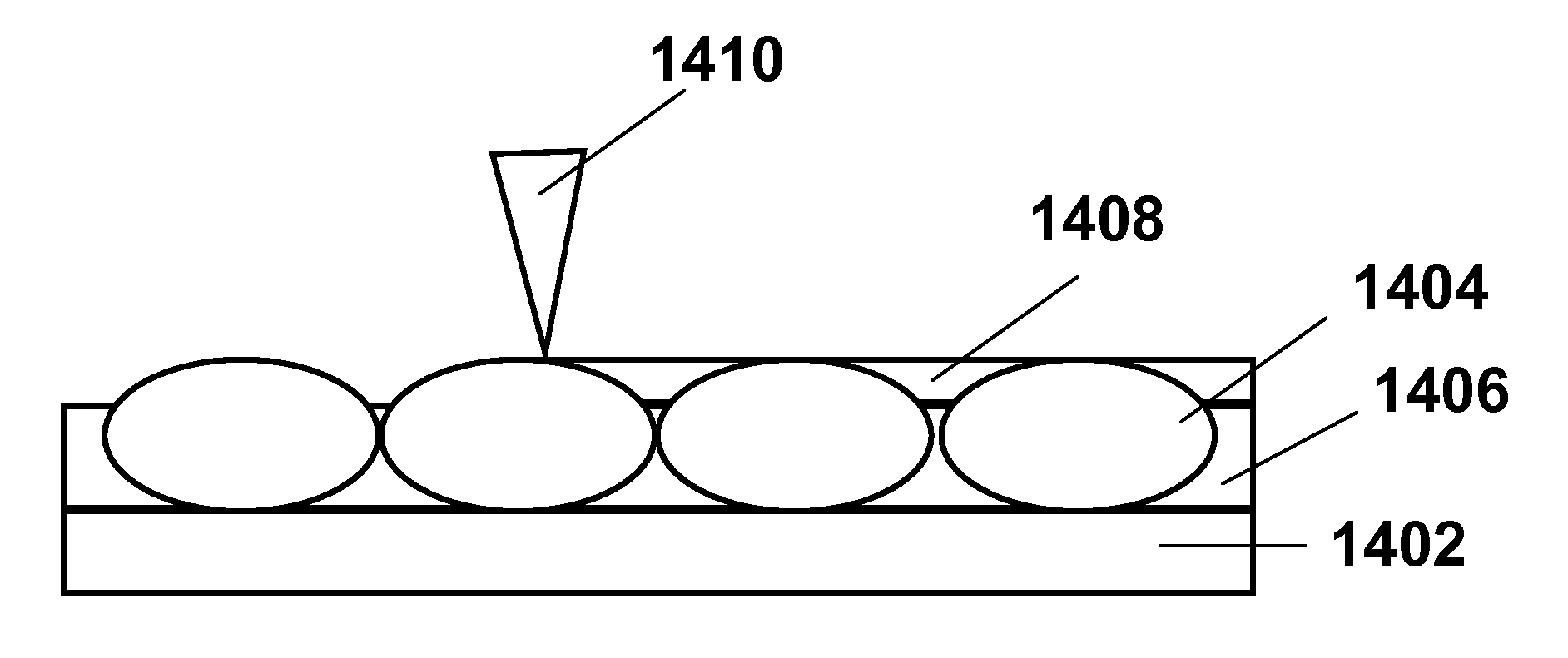
[0107]Three different commercially available PEG's (with number average molecular weights, Mn of 300, 1000, and 8000 g / mole respectively, purchased from Aldrich Chemical) were used at a concentration of 4400 ppm in a custom polyurethane adhesive. The concentration of 4400 ppm corresponds a molar concentration of 5.17×10⁻⁶ for PEG-300, 1.55×10⁻⁶ for PEG-1000, and 1.94×10⁻⁷ for PEG-8000. To provide experimental samples closely simulating an encapsulated electrophoretic display, each polyurethane / PEG mixture was coated at a thickness of 30±2 μm on to a 7 mil (177 μm) poly(ethylene terephthalate) (PET) film coated with ITO, the mixture being coated on to the ITO-covered surface of the film. To provide experimental test units suitable for use in these experiments, pieces of the resultant adhesive-coated film were then laminated at 120° C. and 65 psig (approximately 0.5 mPa) at a speed of 6 inches / minute (approximately 2.5 mm / sec) to a 5 cm by 5 cm PET film covered with a carbon black lay...

example 2

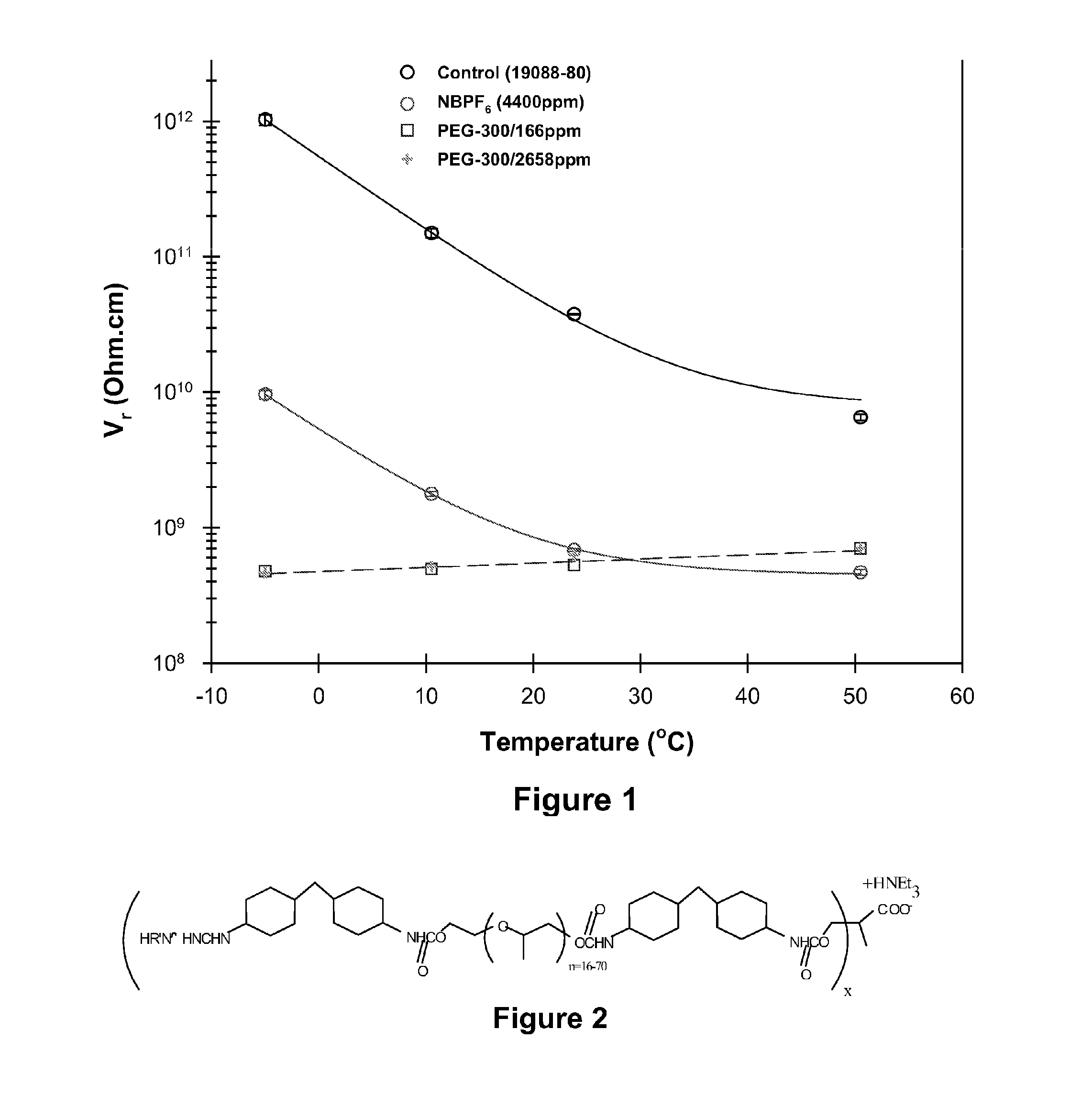
[0110]As already mentioned, the addition of low molecular weight hydroxyl-containing polymers improves the variation of the volume resistivity of polyurethane adhesives with temperature in a manner which the addition of salts does not. A second series of experiments were conducted to illustrate this behavior. Test units were prepared and conditioned in the same way as in Example 1 except that the conditioning was performed for a minimum of only 100 hours, and that the test units contained only no additive, 4400 ppm of tetrabutylammonium hexafluorophosphate, or 166 or 2658 ppm of PEG-300. Volume resistivity measurements were then conducted at temperatures from −5° C. to 50° C., in all cases at 30 percent relative humidity. The results are shown in FIG. 1 of the accompanying drawings; no error bars are shown in this Figure since experimental error is in general less than the size of the symbols used to mark the data points.

[0111]From FIG. 1, it will be seen that the volume resistivity...

example 3

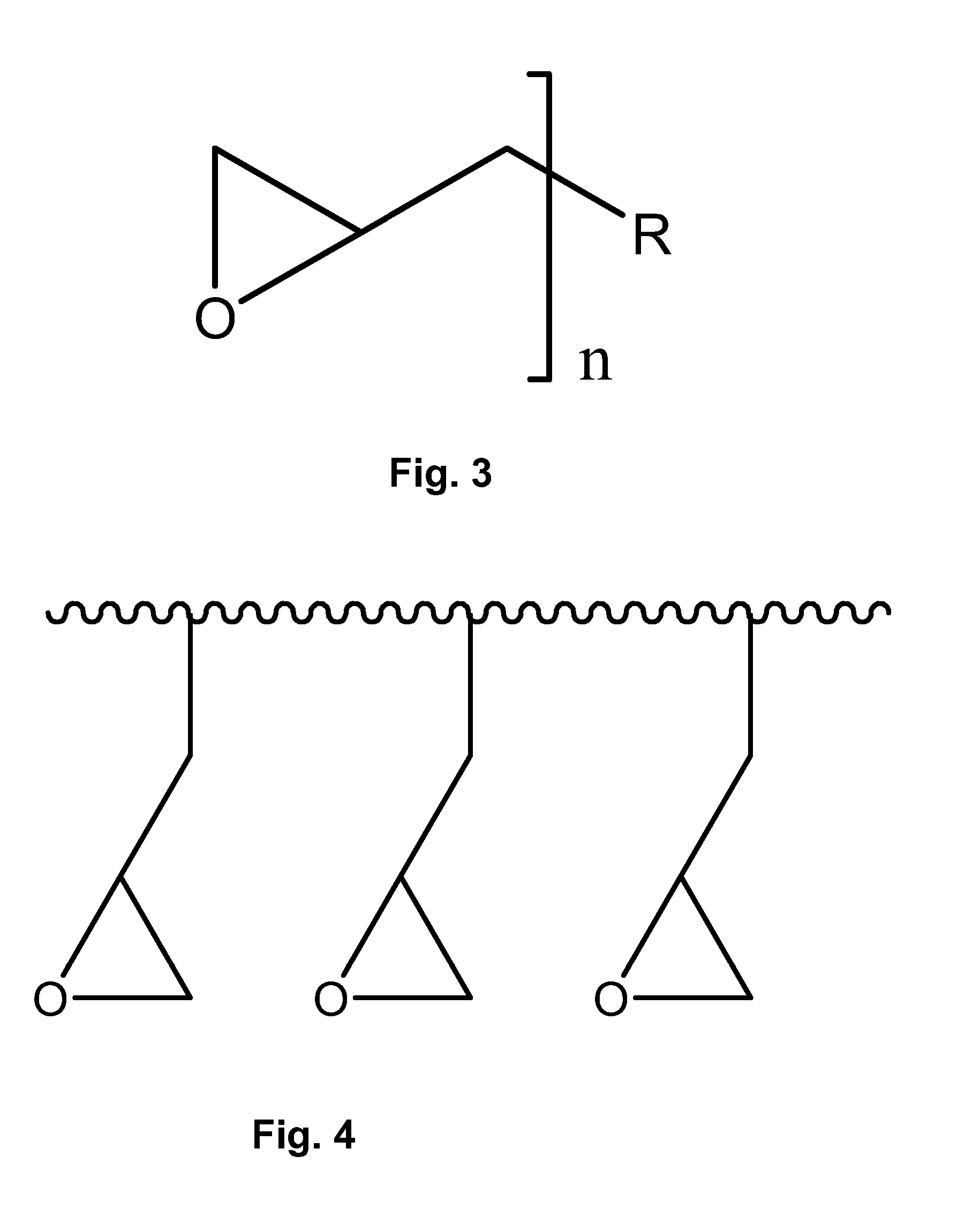
Cross-Linking of Polyurethane Adhesive with N,N-diglycidyl Aniline

[0169]A custom aqueous polyurethane dispersion having a solids content of about 35 percent by weight was coated on to a release sheet and dried in a conveyor oven at 60° C. for approximately 2 minutes, the coating weight of the dispersion being controlled so that an adhesive layer 15 μm thick was formed on the release sheet. To demonstrate the effect of a thermally-activated cross-linking agent, the dispersion used contained 20,000 ppm (based upon the solids content of the dispersion) of N,N-diglycidyl aniline (DGA).

[0170]The resultant adhesive layer was peeled from the release sheet and folded into multiple thicknesses to provide an adhesive layer sufficiently thick for shear modulus testing, which was conducted on a Dynamic Mechanical Analyzer, Model RH2000. A sample of the adhesive was exposed to a temperature of 60° C. for a period of 1000 minutes, then its temperature was raised successively to 70, 80 and 90° C.,...


PUM

PropertyMeasurementUnit
Thicknessaaaaaaaaaa
Thicknessaaaaaaaaaa
Fractionaaaaaaaaaa

Abstract

A first electro-optic display comprises first and second substrates, and an adhesive layer and a layer of electro-optic material disposed between the first and second substrates, the adhesive layer comprising a mixture of a polymeric adhesive material and a hydroxyl containing polymer having a number average molecular weight not greater than about 5000. A second electro-optic display is similar to the first but has an adhesive layer comprising a thermally-activated cross-linking agent to reduce void growth when the display is subjected to temperature changes. A third electro-optic display, intended for writing with a stylus or similar instrument, is produced by forming a layer of an electro-optic material on an electrode; depositing a substantially solvent-free polymerizable liquid material over the electro-optic material; and polymerizing the polymerizable liquid material.

Description

REFERENCE TO RELATED APPLICATIONS[0001]This application is a continuation-in-part of copending application Ser. No. 12 / 046,126, filed Mar. 11, 2008 (Publication No. 2008 / 0218839), which is itself a continuation-in-part of application Ser. No. 11 / 613,259, filed Dec. 20, 2006 (Publication No. 2007 / 0097489, now U.S. Pat. No. 7,349,148, issued Mar. 25, 2008), which is itself a divisional of application Ser. No. 10 / 904,351, filed Nov. 5, 2004 (now U.S. Pat. No. 7,173,752, issued Feb. 6, 2007), which claims benefit of Application Ser. No. 60 / 481,600, filed Nov. 5, 2003, of Application Ser. No. 60 / 481,605, filed Nov. 6, 2003, and of Application Ser. No. 60 / 481,787, filed Dec. 14, 2003.[0002]This application is also a continuation-in-part of copending International Application No. PCT / US2009 / 036756, filed Mar. 11, 2009 (Publication No. WO 2009 / 151675), which claims priority of the aforementioned application Ser. No. 12 / 046,126.[0003]This application is related to:[0004](a) application Ser. ...

Claims


Application Information

Patent Timeline
IPC IPC(8): G02F1/01B32B37/12B32B37/14B32B38/10G02F1/167G02F1/16757
CPCC08J7/16G02F2202/28G02F1/167G02F1/061G02F1/16757G02F2001/1678G02F1/13306G02F2202/022G02F1/172G02F1/1681G02F1/133354G02F1/133514C09J175/04G06F3/03545
Inventor PAOLINI, JR., RICHARD J.MCCREARY, MICHAEL D.HONEYMAN, CHARLES HOWIEWU, BIN
Owner E INK CORPORATION
Why Eureka
Try Eureka