Eureka AIR delivers breakthrough ideas for toughest innovation challenges, trusted by R&D personnel around the world.

X-ray image recording system and x-ray recording method for recording image data with x-ray units for volume reconstruction

Inactive Publication Date: 2011-07-07
FRAUNHOFER GESELLSCHAFT ZUR FOERDERUNG DER ANGEWANDTEN FORSCHUNG EV
View PDF25 Cites 17 Cited by
  • Summary
  • Abstract
  • Description
  • Claims
  • Application Information

AI Technical Summary

Benefits of technology

[0010]It is hence the object of the present invention to make available an X-ray image recording system and an X-ray image recording method with which, in a simple, economical manner and with a simple mechanical construction (in particular the mechanical construction of a standard C-arm system), X-ray projection images of an object can be recorded from different directions and with which, by determining the position of the individual projection images in space (at the moment of their recording), all the required data (position data) for reconstruction of tomographic images from the recorded X-ray projection images can be determined with high precision.
[0019]A particular advantage of the definition according to the invention of precisely one reference direction (to which the orientation data relate) is that, with the help of a single position sensor, which can also possibly be fitted subsequently, all the required data (e.g. during the above-described calibration) can be detected with high accuracy.
[0022]A particular advantage of this system is the possibility of simple integration of this 3D imaging function (in software and / or hardware) in present X-ray units (in particular C-arm X-ray systems) without requiring to undertake mechanical changes.
[0026]In addition to the advantages described already above, the present invention, relative to the systems known from the state of the art, have above all the following advantages:

Problems solved by technology

In this type of imaging, X-rays penetrate the tissue to be imaged and are thereby weakened.
Exact checking of implant positions or assessment of repositioned joint surfaces after fractures is scarcely possible with projection images.
This construction allows significantly smaller and lighter mechanical constructions but has the result that, during a rotation of the C, the object moves out of the image centre.
The systems known from the state of the art have the disadvantage in particular that a plurality of sensors and motors and possibly a device for automatic orientation of the X-ray system must be integrated in a fixed manner in the C-arm.
The mechanical complexity for such a design of an X-ray system is hence expensive.
As a result, the flexibility of the X-ray system is partially lost.
The image recording cannot thus be adapted flexibly to the clinical problem and the desired reconstruction quality.
Finally, the known systems offer no possibility of improving the reconstruction outcome by specific recording of further images.

Method used


Image

  • X-ray image recording system and x-ray recording method for recording image data with x-ray units for volume reconstruction
  • X-ray image recording system and x-ray recording method for recording image data with x-ray units for volume reconstruction
  • X-ray image recording system and x-ray recording method for recording image data with x-ray units for volume reconstruction

Examples


Embodiment Construction

[0032]There are thereby shown:

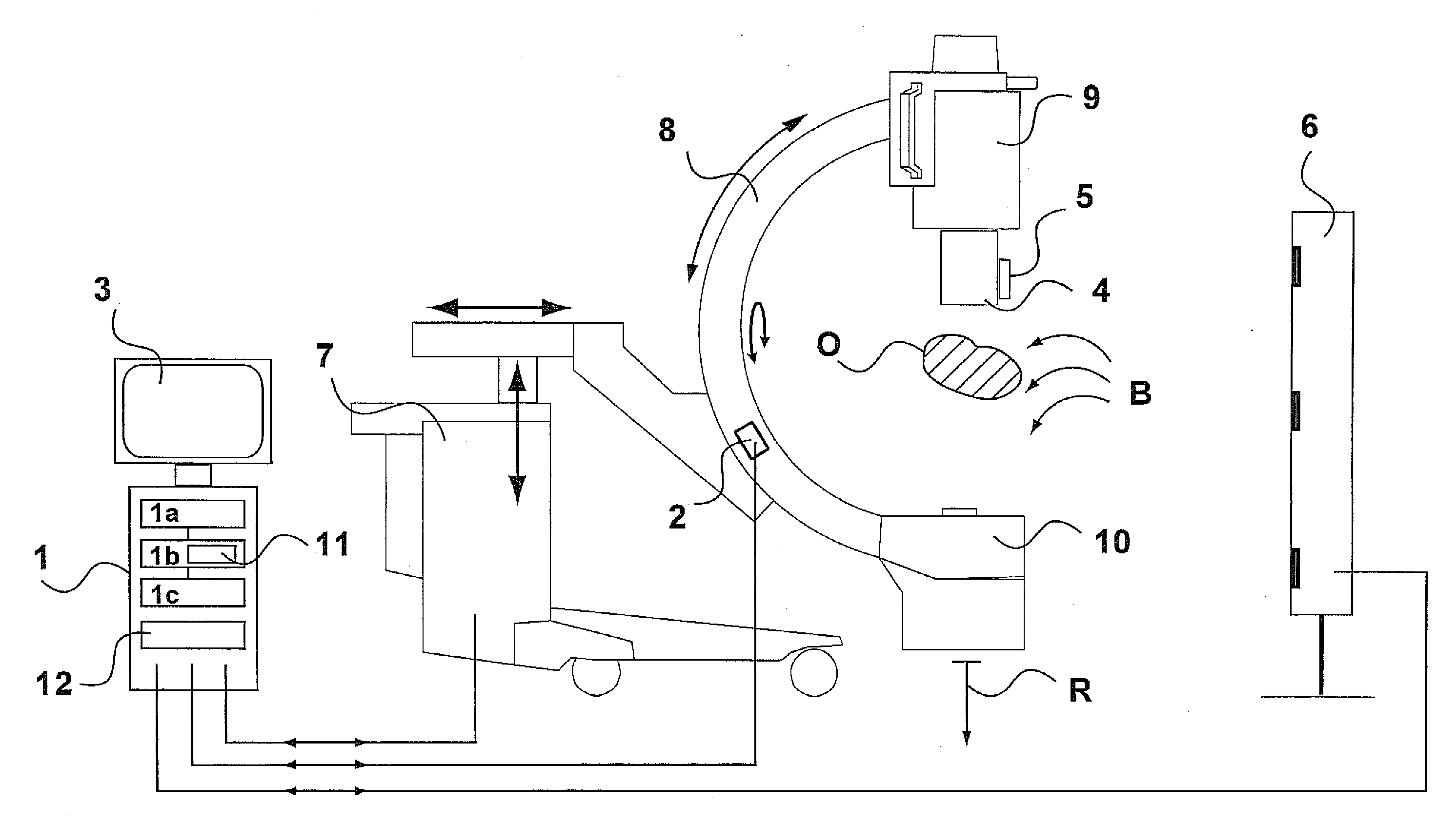
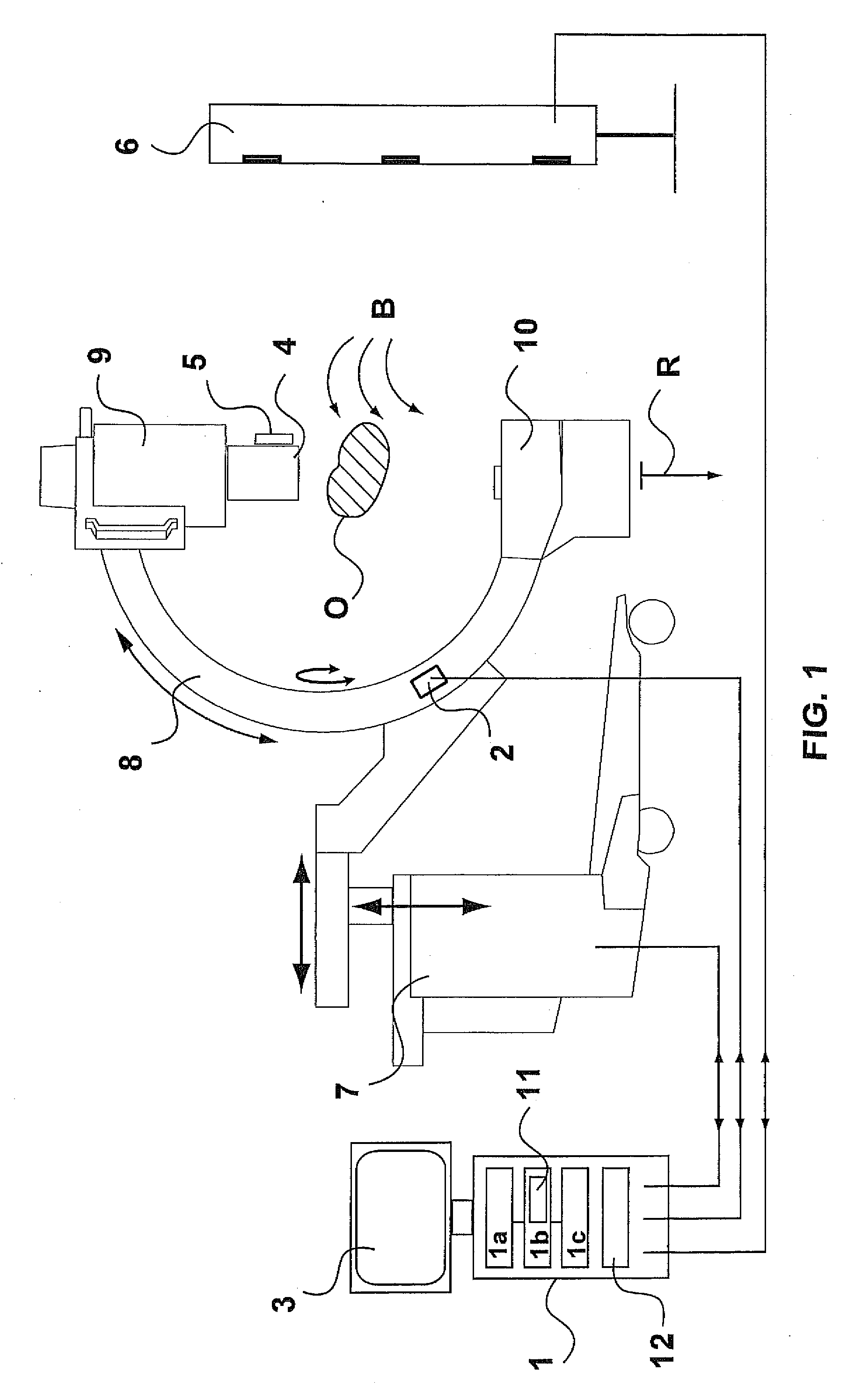
[0033]FIG. 1 the basic configuration of the X-ray image recording system according to this embodiment;

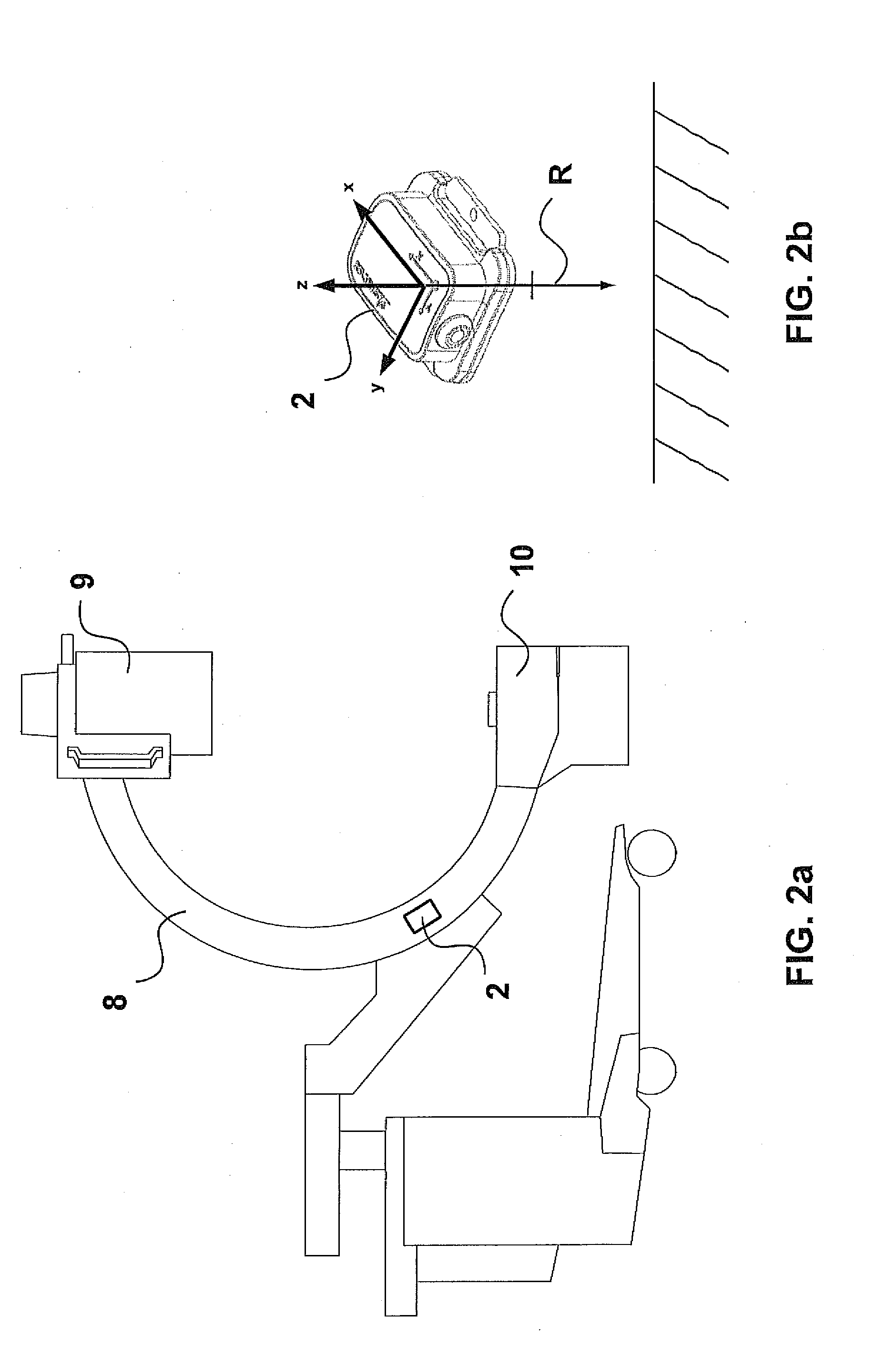
[0034]FIGS. 2a-2b the application and principle of use of the position sensor which is used;

[0035]FIG. 3 the individual movement axes of the recording system, given by way of example;

[0036]FIG. 4 the principle of calibration of the recording system according to FIG. 1;

[0037]FIG. 5 support points determined during a calibration and support points of a calibration table (LUT), given by way of example and interpolated therefrom;

[0038]FIG. 6 the system components of the system of FIG. 1 during calibration;

[0039]FIGS. 7a-7b the data flow of the software components of the example system of FIG. 1 during calibration and during the reconstruction phase.

[0040]FIG. 1 shows an X-ray image recording system according to the present invention in a first embodiment. The X-ray image recording system is constructed on the basis of a standard C-arm. The C-arm 8, at its f...


PUM


Abstract

The present invention relates to an x-ray image recording system for recording x-ray projection images of alignment information for recorded x-ray projection images, comprising an x-ray tube and an x-ray image detector being arranged in the optical path of the x-ray tube for recording x-ray projection images of an object that can be disposed and / or that is disposed between the x-ray tube and the x-ray detector in an imaging region in a locally fixed manner, wherein the x-ray tube and the x-ray detector are disposed in a locally fixed manner relative to each other, and can be moved about the imaging region, at least in sections, a position sensor being disposed relative to the x-ray tube and the x-ray detector in a locally fixed manner, by means of said sensor the current alignment of the x-ray tube and the x-ray detector can be determined relative to a predefined reference direction at the moment of recording an x-ray projection image, and a storage unit for storing recorded x-ray projection images together with the respective current alignment of the x-ray tube and the x-ray detector. The invention comprises a computer being connected to the storage unit for the purpose of data exchange, by means of said computer the position data of the x-ray projection image that are necessary for the calculation of the layered images if the reconstruction can be calculated from the stored, associated current alignment for the purpose of layered image reconstruction based on multiple recorded x-ray projection images for each recorded x-ray projection image utilized.

Description

PRIORITY INFORMATION[0001]The present application is a continuation of PCT Application No. PCT / EP 2009 / 005437, filed on Jul. 27, 2009, that claims priority to German Application No. 102008035736.7, mailed on Jul. 31, 2008. Both applications are incorporated herein by reference in their entireties.BACKGROUND OF THE INVENTION[0002]The present invention relates to an X-ray image recording system (and also to a corresponding X-ray image recording method) for recording X-ray projection images and for recording orientation information for the recorded X-ray projection images. The recording system or the recording method can thereby be achieved in particular within the scope of a commercially available C-arm system which is then configured with suitable hardware- and / or software measures for operation as X-ray image recording system according to the invention.[0003]In medicine, imaging serves for displaying inner regions of a patient and for diagnosis and for checking treatment. During a s...

Claims


Application Information

Patent Timeline
IPC IPC(8): A61B6/03
CPCA61B6/4441A61B6/547A61B6/466
Inventor JANK, EMANUELUHLMANN, ECKART
Owner FRAUNHOFER GESELLSCHAFT ZUR FOERDERUNG DER ANGEWANDTEN FORSCHUNG EV
Why Eureka
Eureka Blog
Learn More