Ceiling fan

a ceiling fan and fan body technology, applied in the direction of positive displacement liquid engine, piston pump, liquid fuel engine, etc., can solve the problems of high cost, long life, and ineffective electrical efficiency, and achieve low cost, easy access, and safe installation

Active Publication Date: 2011-07-07
DELTA T
View PDF26 Cites 36 Cited by
  • Summary
  • Abstract
  • Description
  • Claims
  • Application Information

AI Technical Summary

Benefits of technology

[0016]Additionally low voltage auxiliary modules may be attached to the fan, with a mounting method that is low cost, easily accessible, and safe for installation by any ordinary person, not requiring specific electrical training, qualifications or registration.

Problems solved by technology

Existing ceiling fans are typically powered by high pole number AC induction motors, operating directly from the utility AC line voltage at high degrees of frequency slip, which makes operation very inefficient.
Typical domestic ceiling fans may be optimised for low cost and long life, but not electrical efficiency.
For an AC induction motor, significant losses are incurred by generating the rotor magnetic poles, which are formed by electromagnets powered from the incoming ac line supply.
While rotor losses occur in all AC induction motors, they form a higher proportion of total losses in a ceiling fan motor because of the relatively low mechanical shaft power.
In addition to consuming excessive electricity, the wasted energy is largely dissipated as heat causing substantial temperature rise within the motor, particularly at low speeds where the airflow is substantially reduced.
Cleaning is more frequently required if the fan is located in a food service area where hygiene is important, and where the air may carry additional particles of grease and / or oil making removal of dust from the fan surfaces more difficult.
However, the process of dusting contributes to airborne dust levels by disturbing dust particles from the surface and failing to capture them in the cleaning cloth.
Since the ceiling fan is necessarily mounted above head height, disturbed dust particles can be spread over a wide area and thus present more potential for irritation to sufferers of asthma and allergies than if disturbed at floor level.
None of these address the issue of thoroughly cleaning the entire ceiling fan in a manner which is both safe and effective.
However traditional ceiling fan manufacturers' typically warn against using water during cleaning due to the risk of electric shock to the user, and / or damage to the motor.
This restriction on wet cleaning applies even to fans specifically rated for use in damp or wet areas, since these fans are tested only for water ingress in the most typical direction for the installation, which is generally rainwater falling from above, rather than being cleaned from below.

Method used


Image

  • Ceiling fan
  • Ceiling fan
  • Ceiling fan

Examples


Embodiment Construction

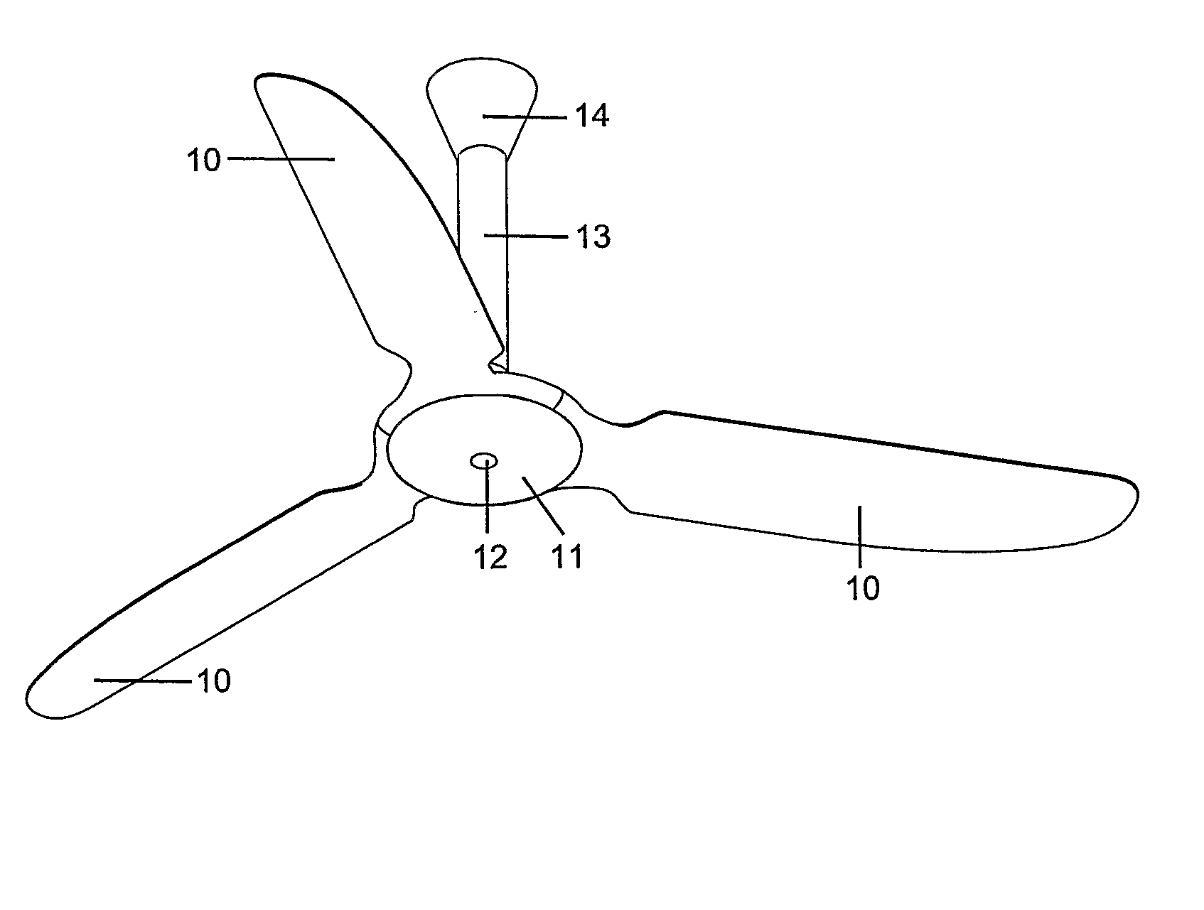
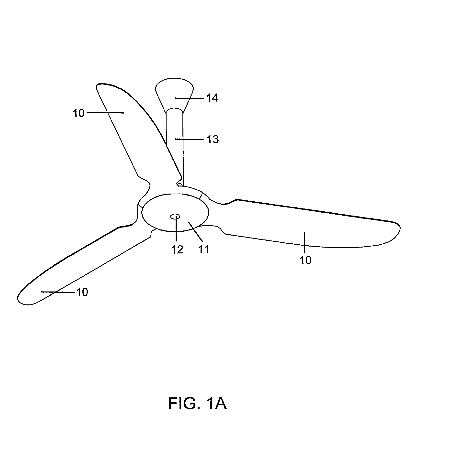
[0034]FIGS. 1a and 1b show a TENV ceiling fan according to an exemplary embodiment. Three fan blades 10 are mounted radially around a central tube assembly 13, with a lower cover 11 with centrally located Infra-Red LED lens 12, fitting tightly to the lower edges of the blades 10, to provide reasonable ingress protection against dust and water from below.

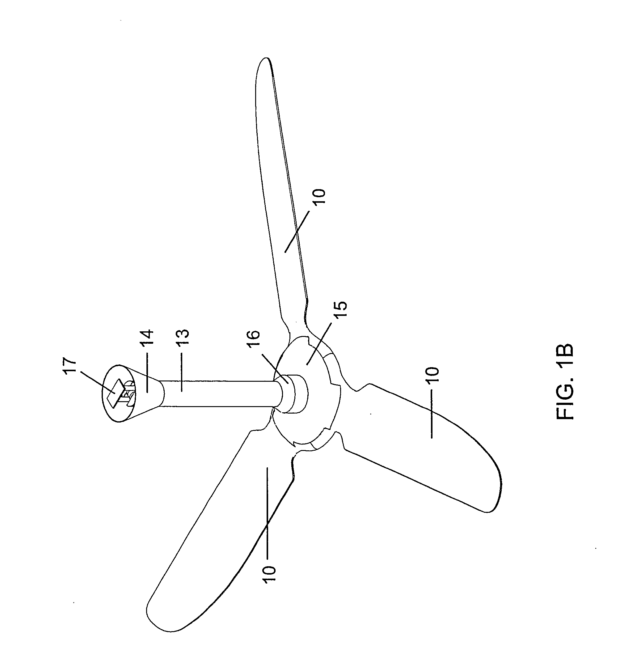
[0035]FIG. 1b illustrates a wiring cover 14 fitted over the top of the tube 13, to conceal the ceiling U-hanger bracket 17. An upper motor cover 15 is located to fit tightly to the upper edges of the blades to provide reasonable ingress protection against dust and water from above.

[0036]FIG. 2 shows an exploded view of the internal components of the tube assembly 13. A tube cap 131 is provided having a clearance hole for a bolt 132, so that when the tube 13 is in its assembled position, bolt 132 passes through tube holes 138, tube cap 131, spacer 141, rubber bush 139 and ceiling U-hanger bracket 17, and is fastened by a nut 133 on th...


PUM


Abstract

A ceiling fan comprising: a fan motor and blade assembly, a mounting tube for suspending the fan motor and blade assembly from a ceiling, and a power supply mounted within the mounting tube configured to power the fan motor. Also a ceiling fan comprising a moulded stator frame, a raised turret integrally moulded within the frame configured to enclose and mount a motor controller, and an external user changeable auxiliary module. Also ceiling fan comprising: a totally enclosed safety extra low voltage fan motor assembly configured to be suspended from an upper side, and a sealing arrangement within the assembly providing a substantial degree of ingress protection against dust and water incident from at least an under side. Also a method comprising providing a ceiling fan comprising moulded stator frame, and mounting an external user changeable auxiliary module to a raised turret integrally moulded within the frame.

Description

FIELD[0001]The present invention relates to ceiling fans, particularly though not solely to a modular Totally Enclosed Non-Ventilated (TENV) ceiling fan driven by an Electronically Commutated (EC) motor with a separated Safety Extra Low Voltage (SELV) Switched Mode Power Supply (SMPS).BACKGROUND[0002]Existing ceiling fans are typically powered by high pole number AC induction motors, operating directly from the utility AC line voltage at high degrees of frequency slip, which makes operation very inefficient. Typical domestic ceiling fans may be optimised for low cost and long life, but not electrical efficiency. For example a typical domestic ceiling fan consumes around 75 W of electrical input power, but only generates around 15 W of mechanical shaft power; an efficiency of just 20%. The balance of 60 W is consumed almost entirely by electrical losses and is dissipated as heat within the motor housing.[0003]For an AC induction motor, significant losses are incurred by generating th...

Claims


Application Information

Patent Timeline
Patent Type & Authority Applications(United States)
IPC IPC(8): F04B17/00F04D29/00
CPCF04D25/088F04D25/068F04D19/002
Inventor NOBLE, ERNEST JOHN
Owner DELTA T
Why Eureka
Try Eureka