

Battery can and alkaline battery
- Summary
- Abstract
- Description
- Claims
- Application Information
AI Technical Summary
Benefits of technology
Problems solved by technology
Method used
Image

Examples
Embodiment Construction
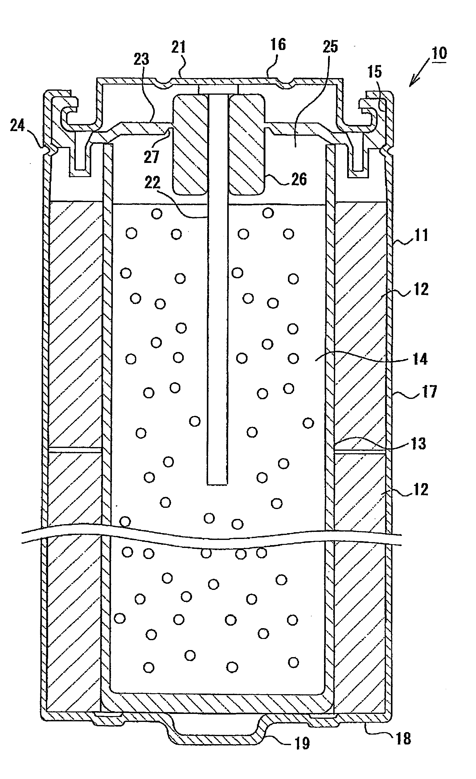
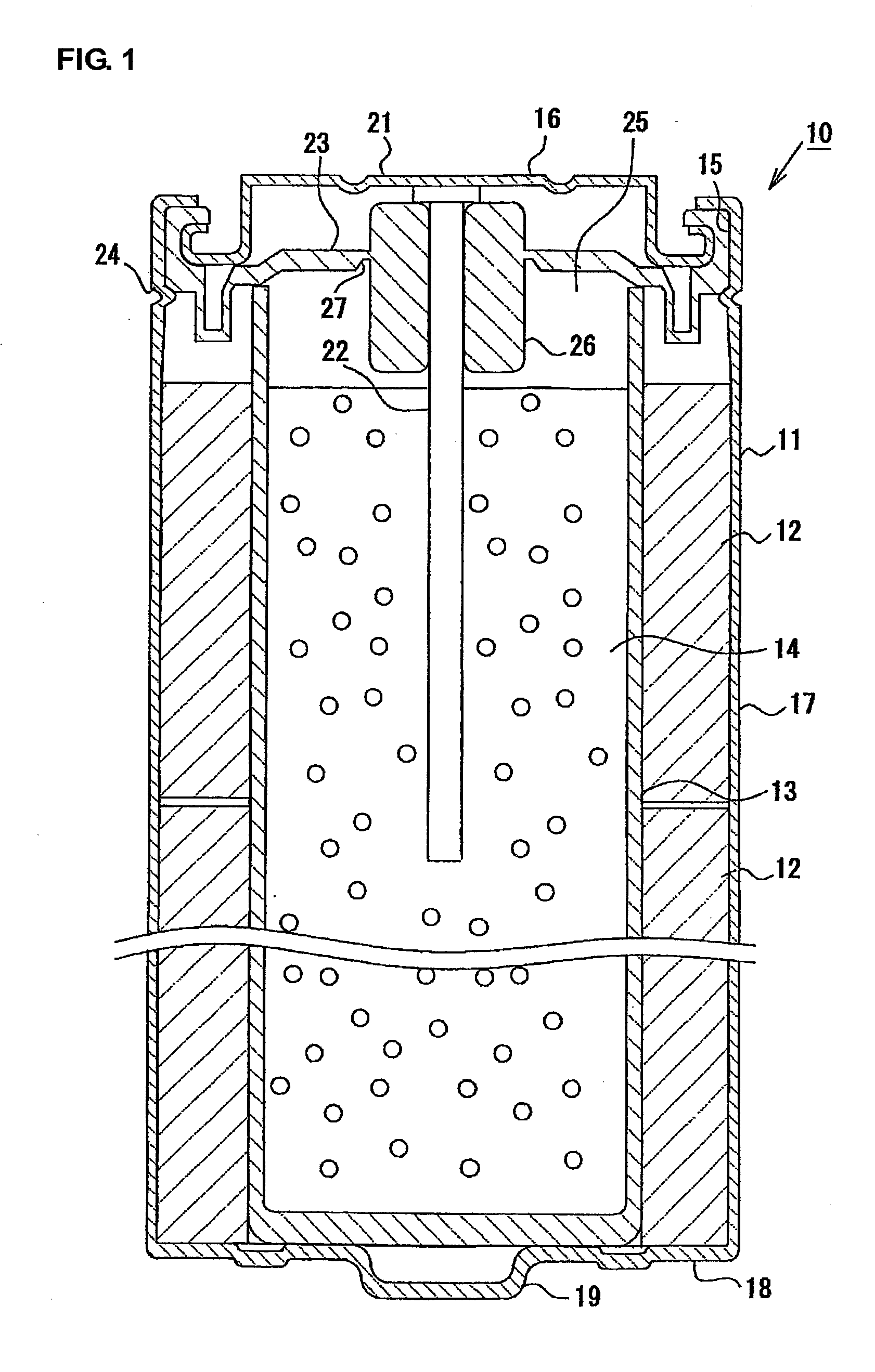
[0025]Hereinafter, the preferred embodiments of this invention is described in reference to the figures. FIG. 1 is a cross-sectional view of the structure of the alkaline battery 10 of the embodiment of this invention, designated as LR03-P4 AAA.
[0026]As shown in FIG. 1, the alkaline battery 10 comprises a cylindrically closed-bottomed cathode can 11 (i.e. the battery can) with a cathode ring-shaped mixture 12 (i.e. the electrode mixture) fitted within the cathode section of the can 11, with closed-bottomed separator 13s set on the inner side of the cathode mixture 12, with an anode gel mixture 14 centrally stored within both separator 13s, and with a current collector 16 attached to the opening 15 of the cathode can 11.
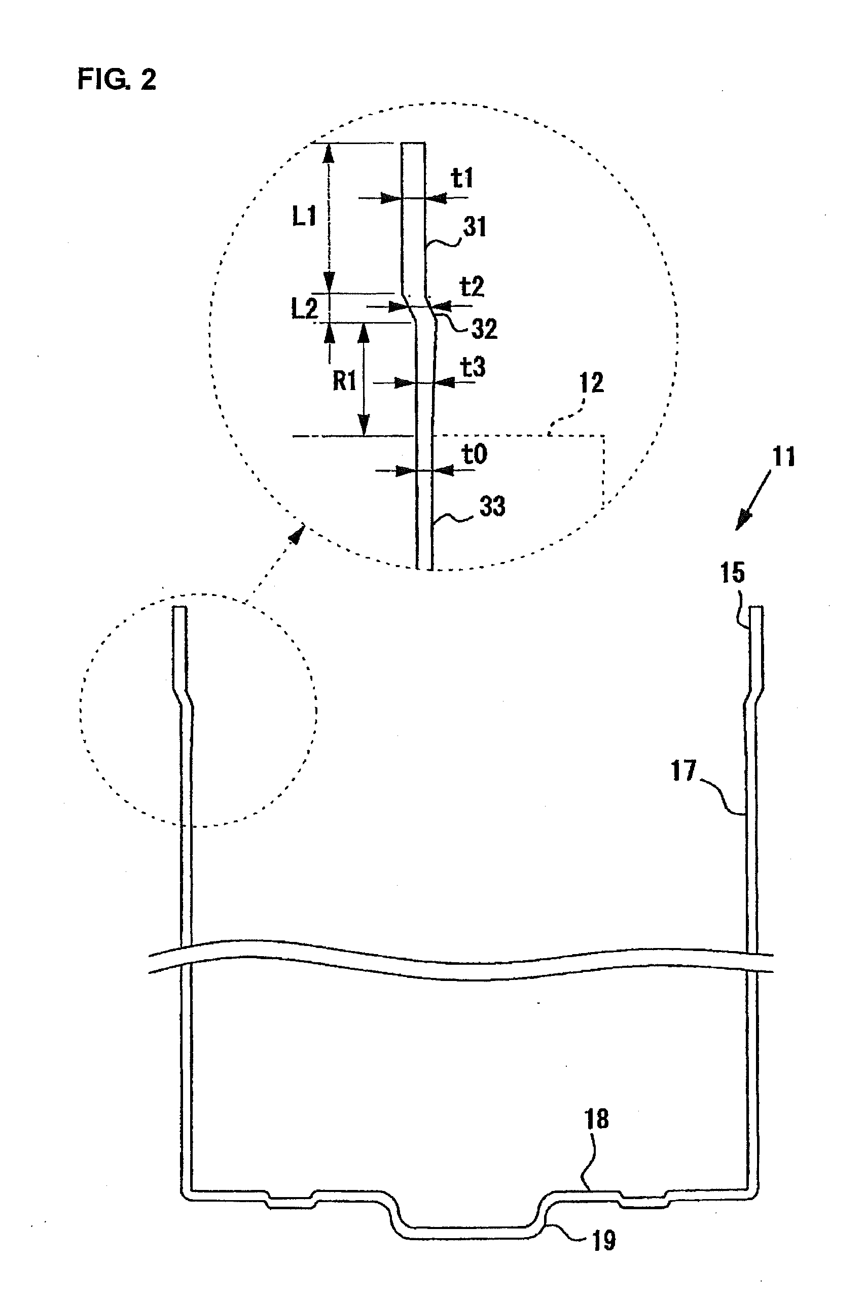
[0027]The cathode can 11 is made of pressed nickel-plated sheet steel forming a closed-bottomed cylinder of an opening 15, a body 17 and a protruding cathode terminal 19 located centrally at the bottom 18.
[0028]The cathode mixture 12 is a granulated powder of electrol...
PUM
 Abstract
Description
Claims
Application Information