
Approach for controlling fuel flow with alternative fuels

Active Publication Date: 2011-07-14
FORD GLOBAL TECH LLC
View PDF75 Cites 36 Cited by
  • Summary
  • Abstract
  • Description
  • Claims
  • Application Information

AI Technical Summary

Benefits of technology

[0001]In some internal combustion engine applications, liquid propane injection can provide some potential benefits relative to gaseous propane injection in ether port fuel injection or direct fuel injection systems. As one example, liquid propane injection provides reduced air displacement that allows for increased air mass to enter an engine cylinder resulting in increased volumetric efficiency relative to gaseous propane injection.
[0003]However, the inventor has recognized several potential issues with such liquid propane fuel systems. For example, during engine shut-off conditions, fuel rail pressure is reduced so that propane cannot be pumped back to the fuel tank via the pressure relief supply line and instead resides in the fuel rail. The liquid propane residing in the fuel rail during engine shut-off conditions may evaporate and leak out of the fuel rail via the fuel injectors into the atmosphere causing increased emissions and reduced fuel economy.
[0005]As an example, the first and second mode may be performed during a vehicle shut-off condition in order to evacuate fuel from the fuel rail. By operating in the first mode, liquid fuel may be evacuated from the fuel rail and returned to the fuel tank. In particular, at vehicle shut-off a fuel rail pressure may be significantly higher than a fuel tank pressure. This pressure difference forces liquid fuel from the fuel rail to the fuel tank. As the liquid fuel evacuates from the fuel rail, the remaining fuel evaporates inot gaseous fuel causing a drop in pressure which stops evacuation of the liquid fuel. Accordingly, by operating in the second mode, the remaining gaseous fuel can be directed to the fuel vapor canister. In this way, evaporative emissions resulting from fuel in the fuel rail evaporating and leaking out of the fuel injectors can be reduced and fuel economy can be increased.

Problems solved by technology

However, the inventor has recognized several potential issues with such liquid propane fuel systems.
The liquid propane residing in the fuel rail during engine shut-off conditions may evaporate and leak out of the fuel rail via the fuel injectors into the atmosphere causing increased emissions and reduced fuel economy.

Method used


Image

  • Approach for controlling fuel flow with alternative fuels
  • Approach for controlling fuel flow with alternative fuels
  • Approach for controlling fuel flow with alternative fuels

Examples


Embodiment Construction

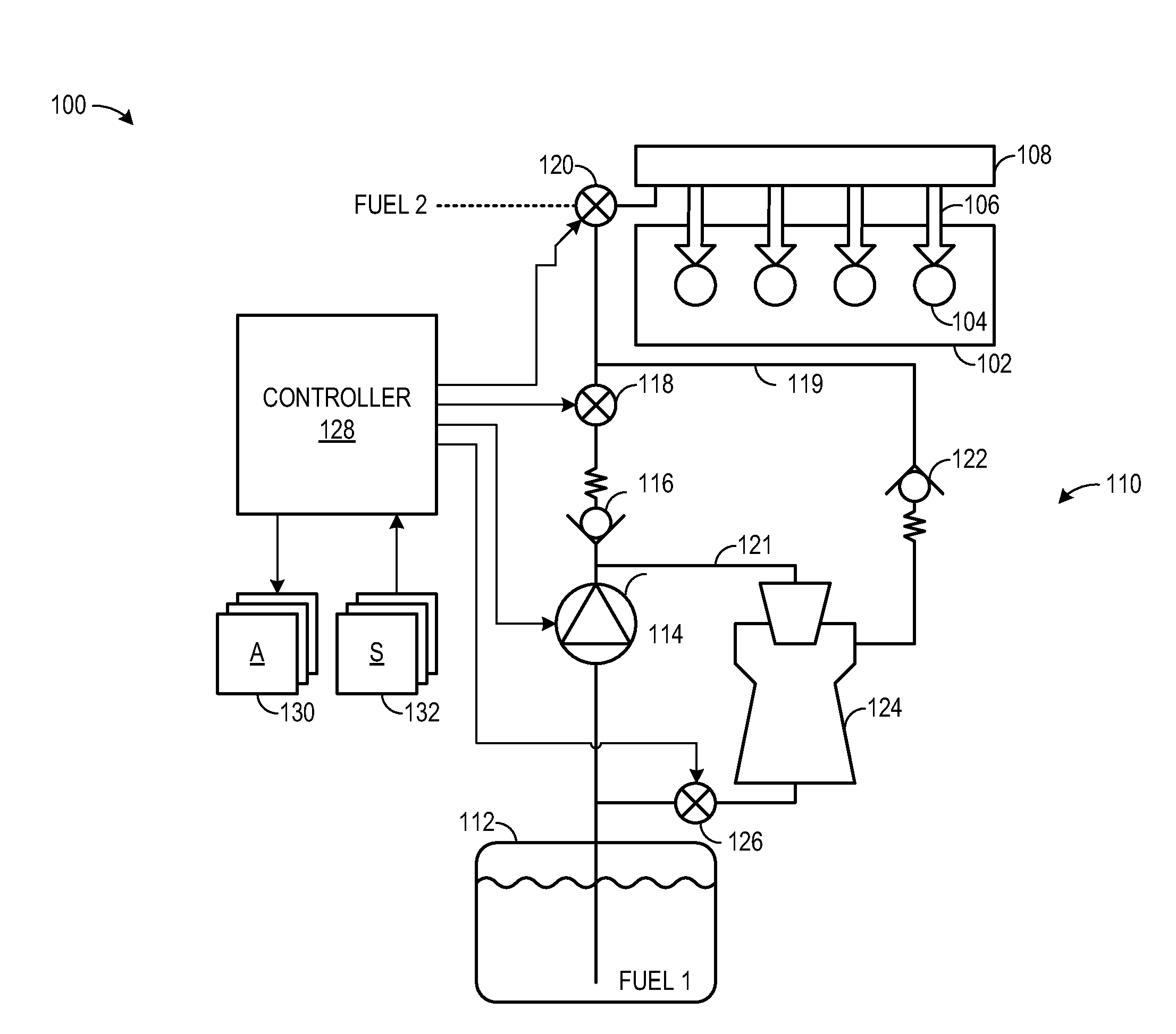
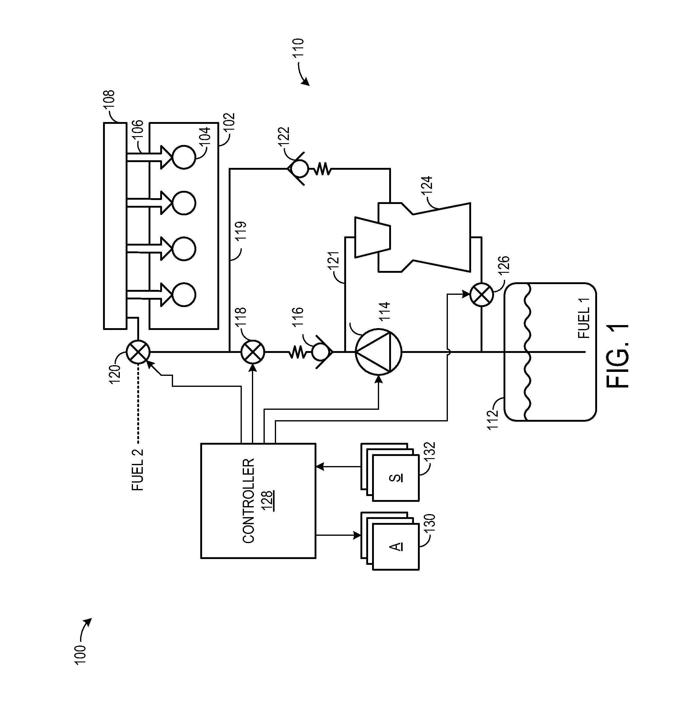
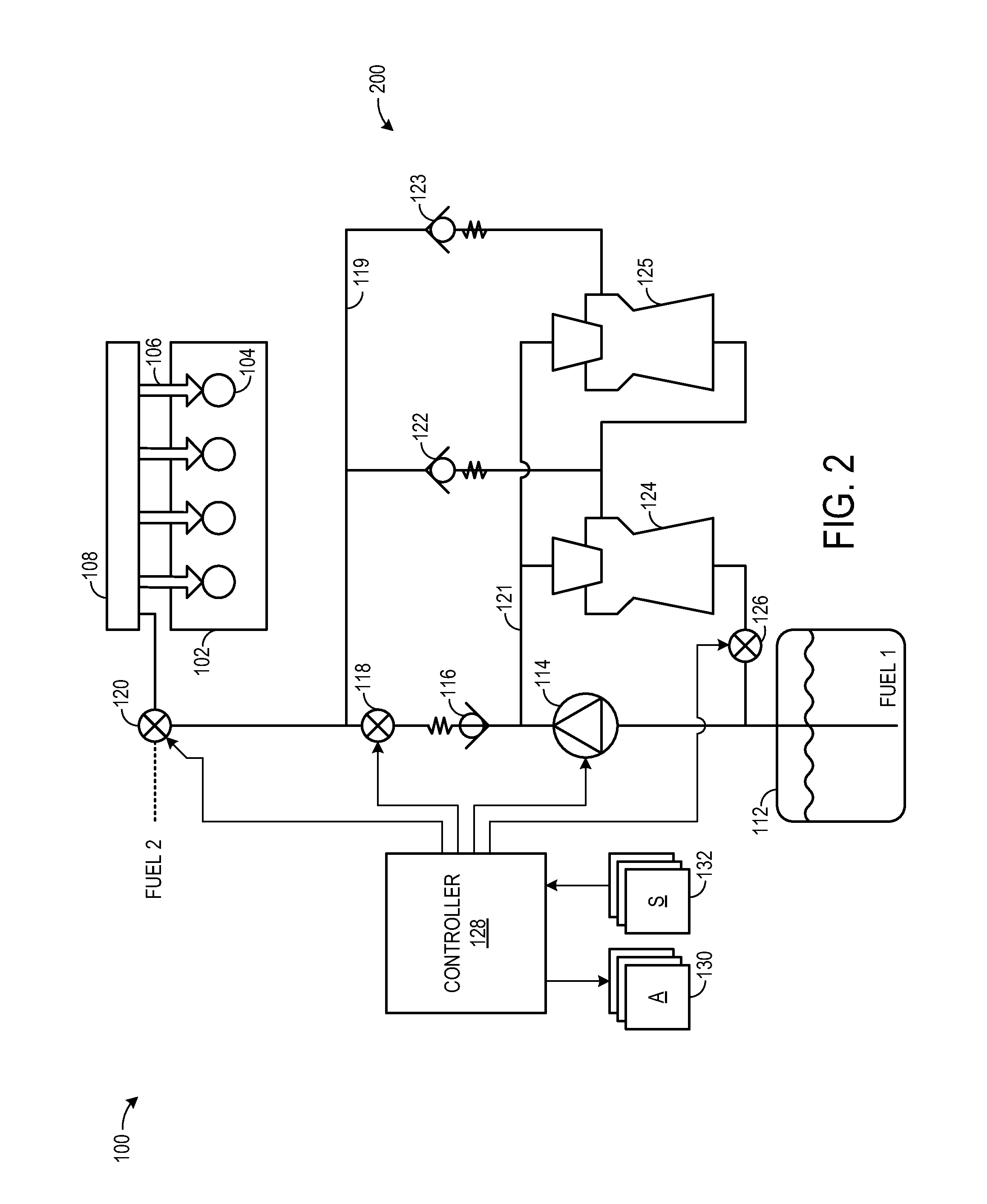
[0017]The present description relates to a fuel system for an internal combustion engine of a vehicle. More particularly, the present description relates to a fuel system that provides versatility so that different fuel types can be injected for combustion, if desired. The fuel system is capable of evacuating the fuel rail upon vehicle shut-off to reduce emissions. Further, since the fuel rail is evacuated different fuels can be selected for combustion upon start-up. For example, the fuel system may include an ejector to evacuate fuel from a fuel rail during an engine shut-off condition of the vehicle. During engine operation, a fuel pump delivers fuel from a fuel tank to the fuel rail. On the other hand, during the engine shut-off condition, the fuel pump provides the motive flow for the ejector to evacuate fuel residing in the fuel rail back into the fuel tank. In some embodiments, the fuel system may include a plurality of ejectors, connected in different stages, to provide a low...


PUM


Abstract

Fuel is evacuated from a fuel rail by directing liquid fuel from the fuel rail to a fuel tank and then by directing gaseous fuel from the fuel rail to a fuel vapor canister.

Description

BACKGROUND AND SUMMARY[0001]In some internal combustion engine applications, liquid propane injection can provide some potential benefits relative to gaseous propane injection in ether port fuel injection or direct fuel injection systems. As one example, liquid propane injection provides reduced air displacement that allows for increased air mass to enter an engine cylinder resulting in increased volumetric efficiency relative to gaseous propane injection.[0002]A typical liquid injection propane fuel system for an internal combustion engine supplies liquid propane from a pressurized tank via a fuel pump to a fuel rail. The liquid propane is injected from the fuel rail to cylinders of the internal combustion engine via fuel injectors. Excess fuel can be returned to the pressurized tank during operation via a pressure relief supply line.[0003]However, the inventor has recognized several potential issues with such liquid propane fuel systems. For example, during engine shut-off conditi...

Claims


Application Information

Patent Timeline
IPC IPC(8): F02M37/04F02M37/00
CPCF02M37/0064F02M25/089F02D19/0605F02D19/0615Y02T10/36F02D19/0647F02D19/0676F02D19/0684F02D19/0694F02D19/0628Y02T10/30
Inventor PURSIFULL, ROSS DYKSTRAULREY, JOSEPH NORMAN
Owner FORD GLOBAL TECH LLC
Learn More