Rotary Steerable Tool Employing a Timed Connection

a timed connection and tool technology, applied in the direction of drilling pipes, drilling rods, directional drilling, etc., can solve the problems of increasing the number of valves required, increasing the complexity of tool assembly procedures, and requiring a large number of controllable components, so as to improve tool reliability, simplify assembly and testing protocols, and reduce fabrication costs

Inactive Publication Date: 2011-07-14
SCHLUMBERGER TECH CORP
View PDF38 Cites 0 Cited by
  • Summary
  • Abstract
  • Description
  • Claims
  • Application Information

AI Technical Summary

Benefits of technology

[0009]Exemplary embodiments of the present invention may advantageously provide several technical advantages. For example, the present invention makes use of hydraulics and electronics modules that are configured as stand-alone assemblies. As such, these modules may be essentially fully assembled and tested independent of one another prior to the assembly of the final steering tool. This feature of the invention advantageously simplifies the assembly and testing protocol of the hydraulics and electronics modules and therefore tends to improve tool reliability and reduce fabrication costs. This feature of the invention also tends to improve the serviceability of the tool in that a failed module (or simply a module needing service) may be easily removed from the tool and replaced and / or repaired.
[0010]The use of distinct hydraulics and electronics modules tends to be further advantageous in that it provides for physical isolation of the sensitive electronics components from hydraulic oil and drilling fluid in the hydraulics module. Moreover, the invention enables the available volume under the hydraulics sleeve to be used as a hydraulic fluid reservoir, thereby obviating the need for a separate reservoir. This can be particularly advantageous in small diameter tools in which space is at a premium.

Problems solved by technology

Spring biased retraction of the blades advantageously reduces the number of valves required to control the blades, however, a significant number of controllable components are still required.
The above-described prior art steering tools employ complex electronic circuitry in order to control the hydraulic actuation of the blades.
For example, deployment of the electronic circuitry and the hydraulic components in a common housing tends to complicate tool assembly procedures (especially in small diameter “slim” tools).
Moreover, disassembly of the entire tool is commonly required when problems are identified during assembly or testing of the tool.
Such disassembly and the subsequent reassembly are time consuming and expensive.

Method used


Image

  • Rotary Steerable Tool Employing a Timed Connection
  • Rotary Steerable Tool Employing a Timed Connection
  • Rotary Steerable Tool Employing a Timed Connection

Examples


Embodiment Construction

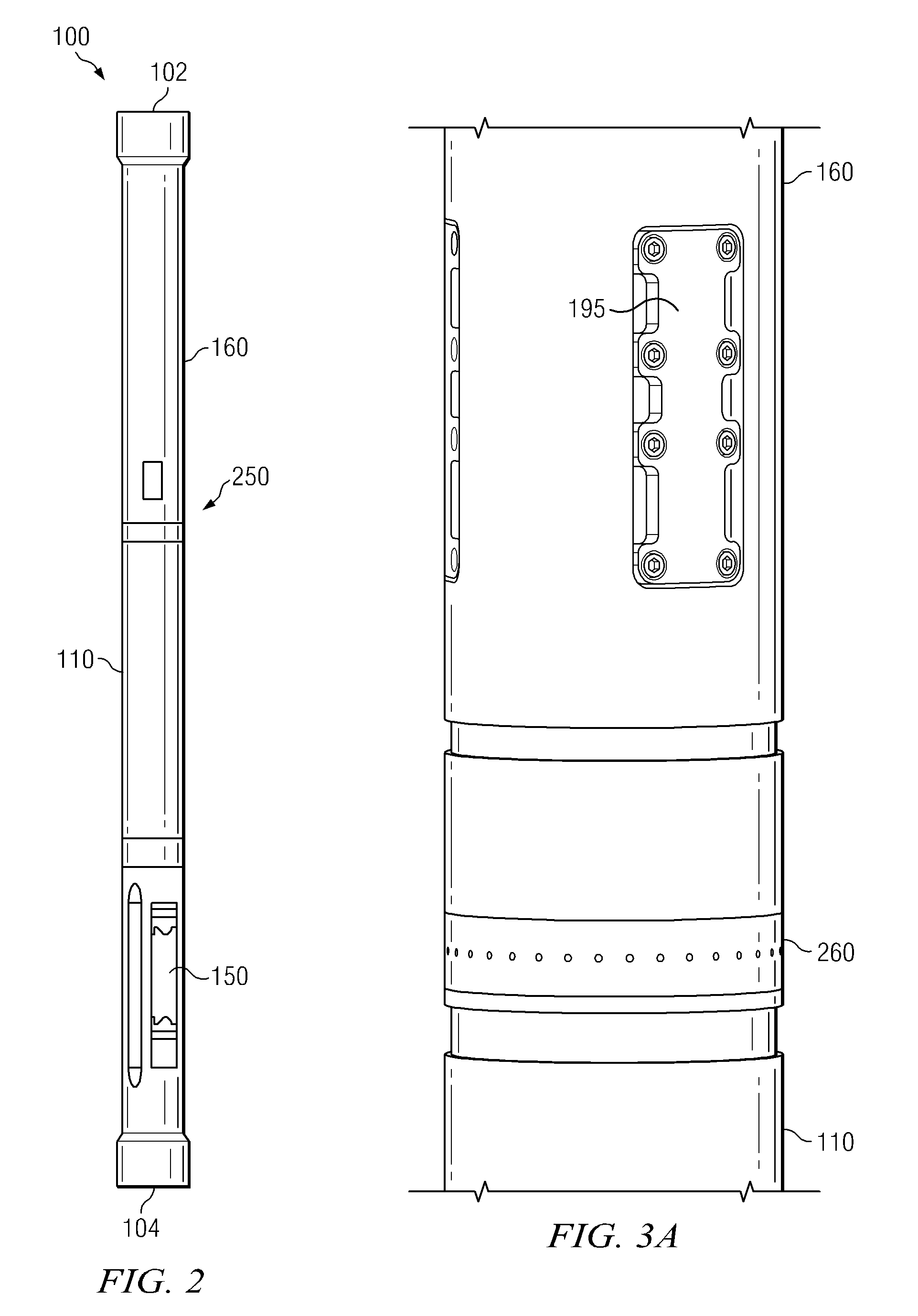
[0023]Referring first to FIGS. 1 through 7, it will be understood that features or aspects of the embodiments illustrated may be shown from various views. Where such features or aspects are common to particular views, they are labeled using the same reference numeral. Thus, a feature or aspect labeled with a particular reference numeral on one view in FIGS. 1 through 7 may be described herein with respect to that reference numeral shown on other views.

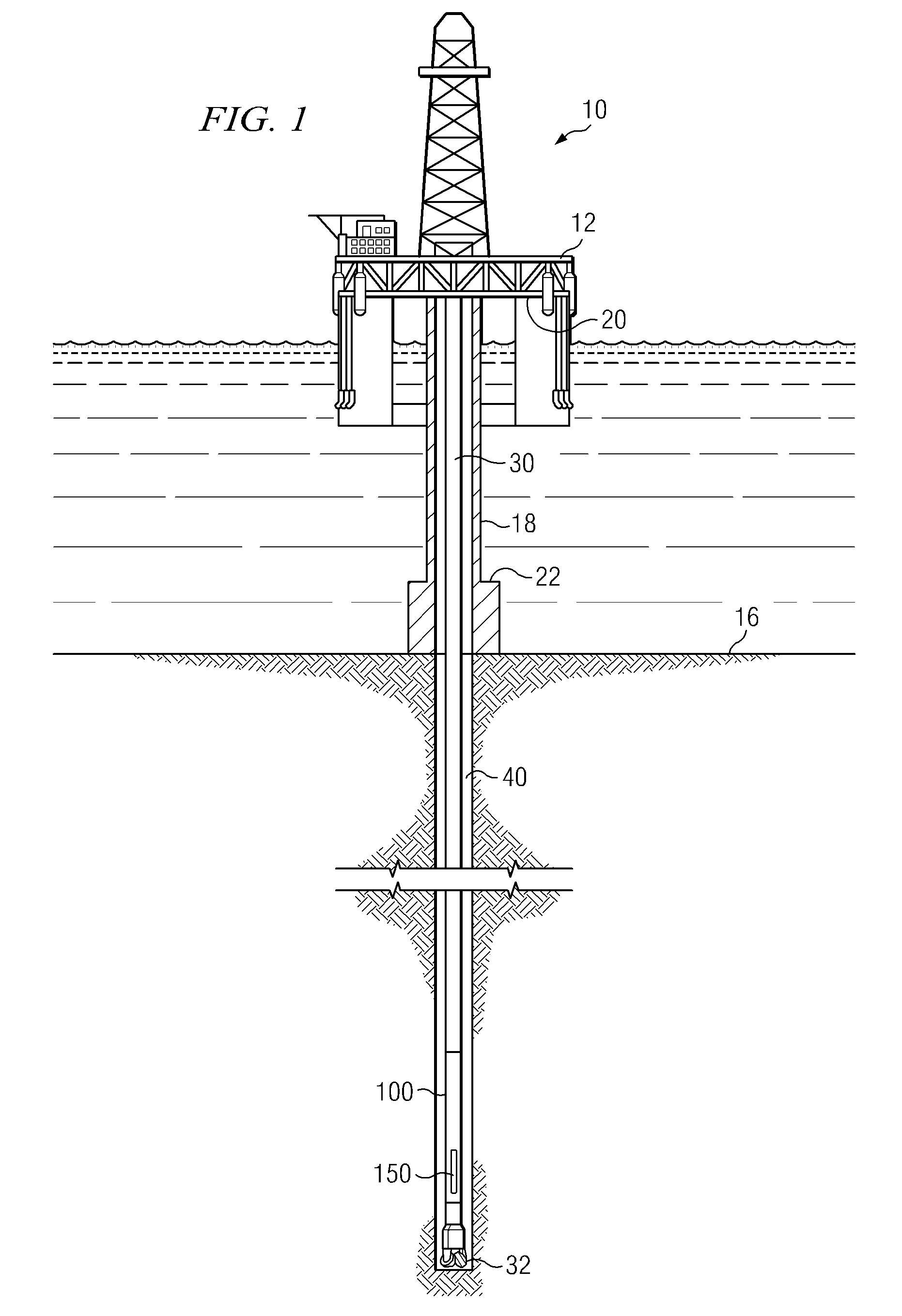
[0024]FIG. 1 illustrates a drilling rig 10 suitable for the deployment of exemplary embodiments of the present invention. In the exemplary embodiment shown on FIG. 1, a semisubmersible drilling platform 12 is positioned over an oil or gas formation (not shown) disposed below the sea floor 16. A subsea conduit 18 extends from deck 20 of platform 12 to a wellhead installation 22. The platform may include a derrick and a hoisting apparatus for raising and lowering the drill string 30, which, as shown, extends into borehole 40 and includes...


PUM


Abstract

A downhole steering tool includes distinct hydraulic and electronics modules deployed about a shaft. The hydraulics module includes a plurality of hydraulically actuated blades. The electronics module includes electronic circuitry configured to control blade actuation. The hydraulics and electronics modules are physically and electrically connected to one another via a timed connection.

Description

RELATED APPLICATIONS[0001]None.FIELD OF THE INVENTION[0002]The present invention relates generally to downhole steering tools. More particularly, the invention relates to a rotary steerable tool including an electronics housing physically and electrically connected to a blade housing via a timed connection.BACKGROUND OF THE INVENTION[0003]Directional control has become increasingly important in the drilling of subterranean oil and gas wells, with a significant proportion of current drilling activity involving the drilling of deviated boreholes. Such deviated boreholes often have complex profiles, including multiple doglegs and a horizontal section that may be guided through thin, fault bearing strata, and are typically utilized to more fully exploit hydrocarbon reservoirs.[0004]Deviated boreholes are often drilled using downhole steering tools, such as two-dimensional and three-dimensional rotary steerable tools. Certain rotary steerable tools make use of a plurality of independentl...

Claims


Application Information

Patent Timeline
Patent Type & Authority Applications(United States)
IPC IPC(8): E21B7/08E21B44/00E21B7/06
CPCE21B7/06
Inventor DEOLALIKAR, NEELESHDAS, PRALAY
Owner SCHLUMBERGER TECH CORP
Why Eureka
Try Eureka