Reaming tool

a tool and tool body technology, applied in the field of reaming tools, can solve the problems of limited rotation of casing strings, inconvenient reaming of casing strings, and inability to transfer torque, and achieve the effect of facilitating reaming of bores

Active Publication Date: 2011-07-14
DEEP CASING TOOLS LTD
View PDF8 Cites 8 Cited by
  • Summary
  • Abstract
  • Description
  • Claims
  • Application Information

AI Technical Summary

Benefits of technology

[0010]a reaming member, wherein relative rotation between the body and the shaft facilitates reaming of the bore by the reaming member.
[0023]a reaming member, wherein relative rotation between the body and the shaft facilitates reaming of the bore by the reaming member.

Problems solved by technology

When running the string into the bore, the string commonly encounters obstructions in the bore including, for example, ledges extending into the bore, partially collapsed regions of a formation, or drill cuttings lying on the lower side of an inclined bore, whereby the bore obstructions may prevent or limit further formation, completion or operation of the bore.
However, casings and casing couplings are generally not suited to transferring torque and rotation of the casing string may be limited.
Furthermore, rotating the casing string greatly complicates the drive and coupling arrangements required at surface.

Method used


Image

  • Reaming tool
  • Reaming tool
  • Reaming tool

Examples


first embodiment

[0058]According to a third aspect of the present invention there is provided a tubular string assembly comprising a reaming tool according to the present invention.

[0059]According to a fourth aspect of the present invention there is provided a seal element for use in a sealing a rotary connection, the seal element adapted to permit sealed relative rotation of the rotary connection. The seal element may comprise a substrate manufactured, for example, from aluminium, aluminium alloy, phosphor bronze, ceramic or other suitable material, the substrate having a layer or coating of hard material. The coating may comprise a tungsten, carbide or cobalt or other hard material.

[0060]According to a fifth aspect of the present invention, there is provided a reaming tool for use in reaming a bore, the tool comprising:

[0061]a body adapted for location in a bore, the body defining a rotor of a rotary drive arrangement;

[0062]a shaft adapted for location in the body, the shaft defining a stator of t...

fifth embodiment

[0066]According to another aspect of the present invention there is provided a tubular string assembly comprising a reaming tool according to the present invention.

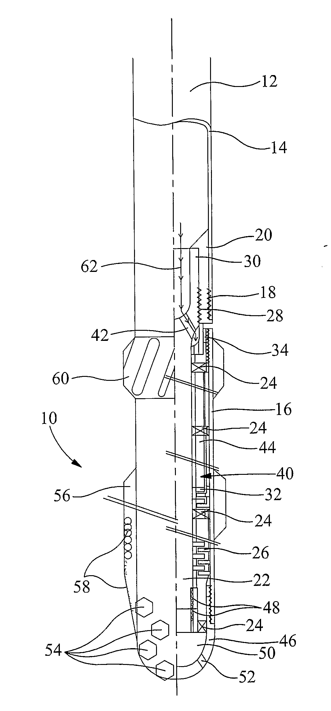
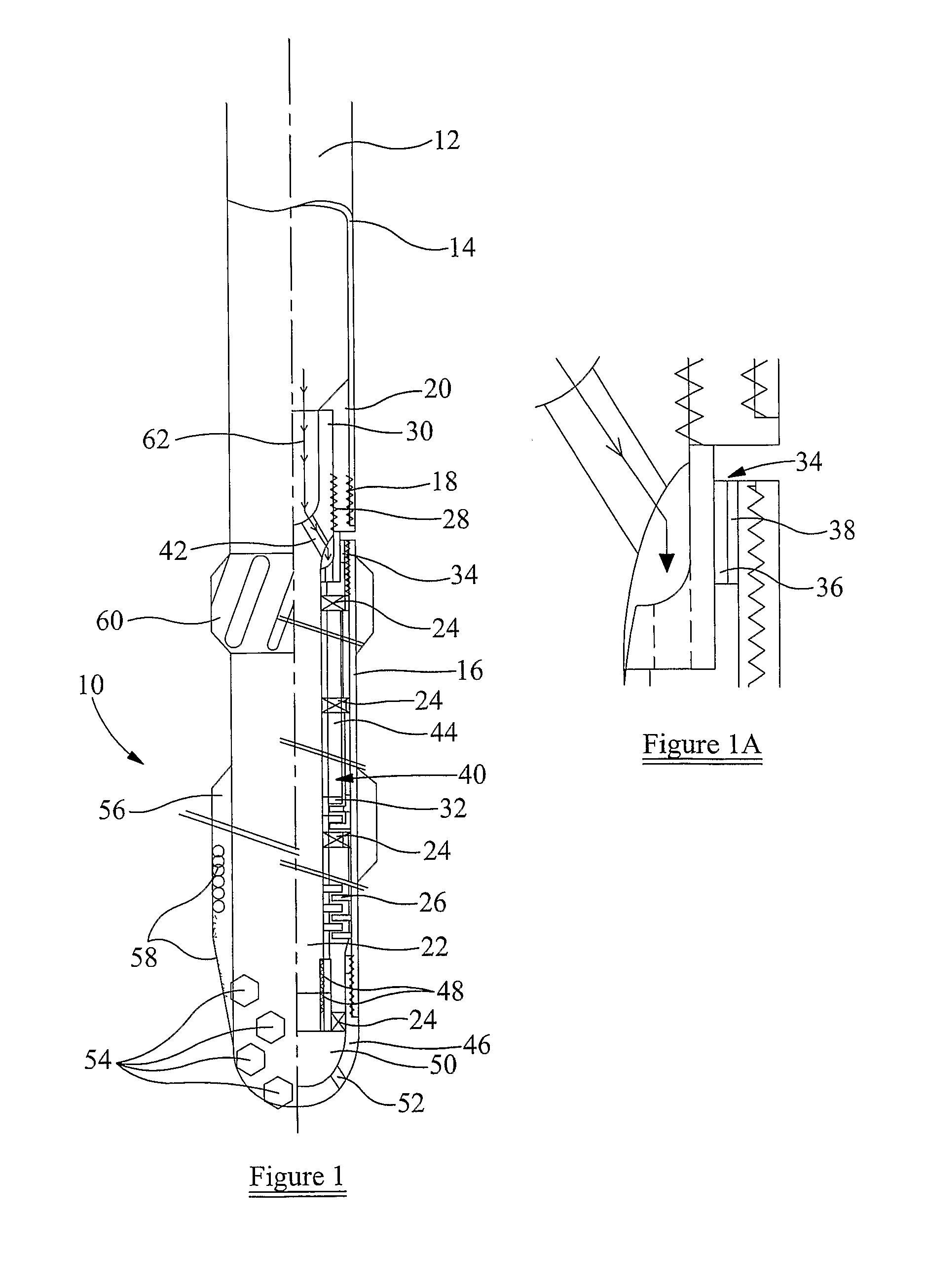
[0067]Referring initially to FIG. 1 of the drawings, there is shown a partial longitudinal sectional view of a reaming tool 10 according to a first embodiment of the present invention. The tool 10 is adapted for location in a bore (not shown).

[0068]In the embodiment shown in FIG. 1, the tool 10 is adapted to be coupled to a tubular component, such as casing 12, via a connector in the form of crossover sub 14, though it will be understood that any suitable coupling may be used. The tool 10 comprises a body 16 coupled to the connector 14 by connection 18. A seal 20 is provided between the body 16 and the connector 14 to substantially prevent fluid leakage between the connector 14 and the body 16. A shaft 22 is mounted within the body 16 on radial bearings 24 and a thrust bearing 26 is provided to axially restrain the shaft ...


PUM


Abstract

A reaming tool for use in reaming a bore includes a body adapted for location in a bore. The body defines a rotor of a rotary drive arrangement. A shaft adapted for location is disposed in the body. The shaft defines a stator of the rotary drive arrangement. A seal element is disposed between the shaft and the body. The seal element defines a bearing surface for permitting sealed relative rotation of the rotary drive arrangement. The tool includes a reaming member, wherein relative rotation between the body and the shaft facilitates reaming of the bore by the reaming member.

Description

CROSS REFERENCE TO RELATED APPLICATIONS[0001]This is a continuation of International Application No. PCT / GB / 2009 / 01601 filed on 26 Jun. 2009. Priority is claimed from British Patent Application No. GB 0811809.3 filed on 27 Jun. 2008.STATEMENT REGARDING FEDERALLY SPONSORED RESEARCH OR DEVELOPMENT[0002]Not ApplicableFIELD OF THE INVENTION[0003]This invention relates to a reaming tool and, in particular, but not exclusively, to a reaming tool for use in a bore, such as a wellbore or the like.BACKGROUND TO THE INVENTION[0004]In the oil and gas industry, in order to access hydrocarbon-bearing or geothermal formations, one or more bores may be drilled from surface, the bores typically being lined with sections of metal tubes, known as casings. A number of casings are coupled together as a casing string, the string being run into the bore substantially without rotation. The annulus between the casings and the bore is subsequently filled and sealed with cement to secure the casings in place...

Claims


Application Information

Patent Timeline
Patent Type & Authority Applications(United States)
IPC IPC(8): E21B4/00E21B4/04E21B7/20E21B4/02E21B7/00F16J15/16
CPCE21B4/02E21B17/14E21B10/26E21B7/208E21B10/28F16J15/16F16J15/166F16J15/28F16J15/3284F16J15/453F16J15/50F16J15/54
Inventor SCOTT, EDWARD D.DAVIS, LANCE S.
Owner DEEP CASING TOOLS LTD
Why Eureka
Try Eureka