
Aircraft frame and method for obtaining the same

a frame and aircraft technology, applied in the field of new design of aircraft frames, can solve the problems of high number of segments or partitions of frames, high assembly labor, and long assembly process of frames, and achieve the effects of reducing assembly times, reducing recurring costs, and simplifying operations

Inactive Publication Date: 2011-07-14
AIRBUS OPERATIONS SL
View PDF3 Cites 6 Cited by
  • Summary
  • Abstract
  • Description
  • Claims
  • Application Information

AI Technical Summary

Benefits of technology

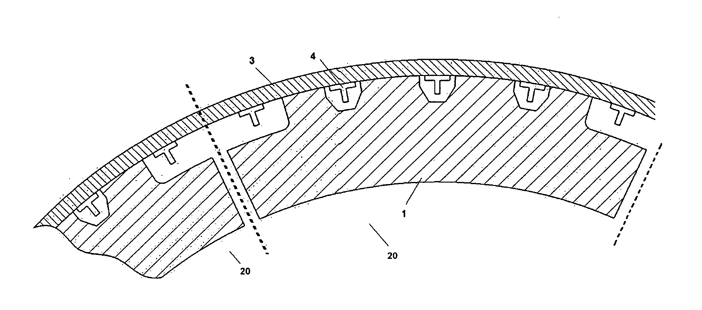
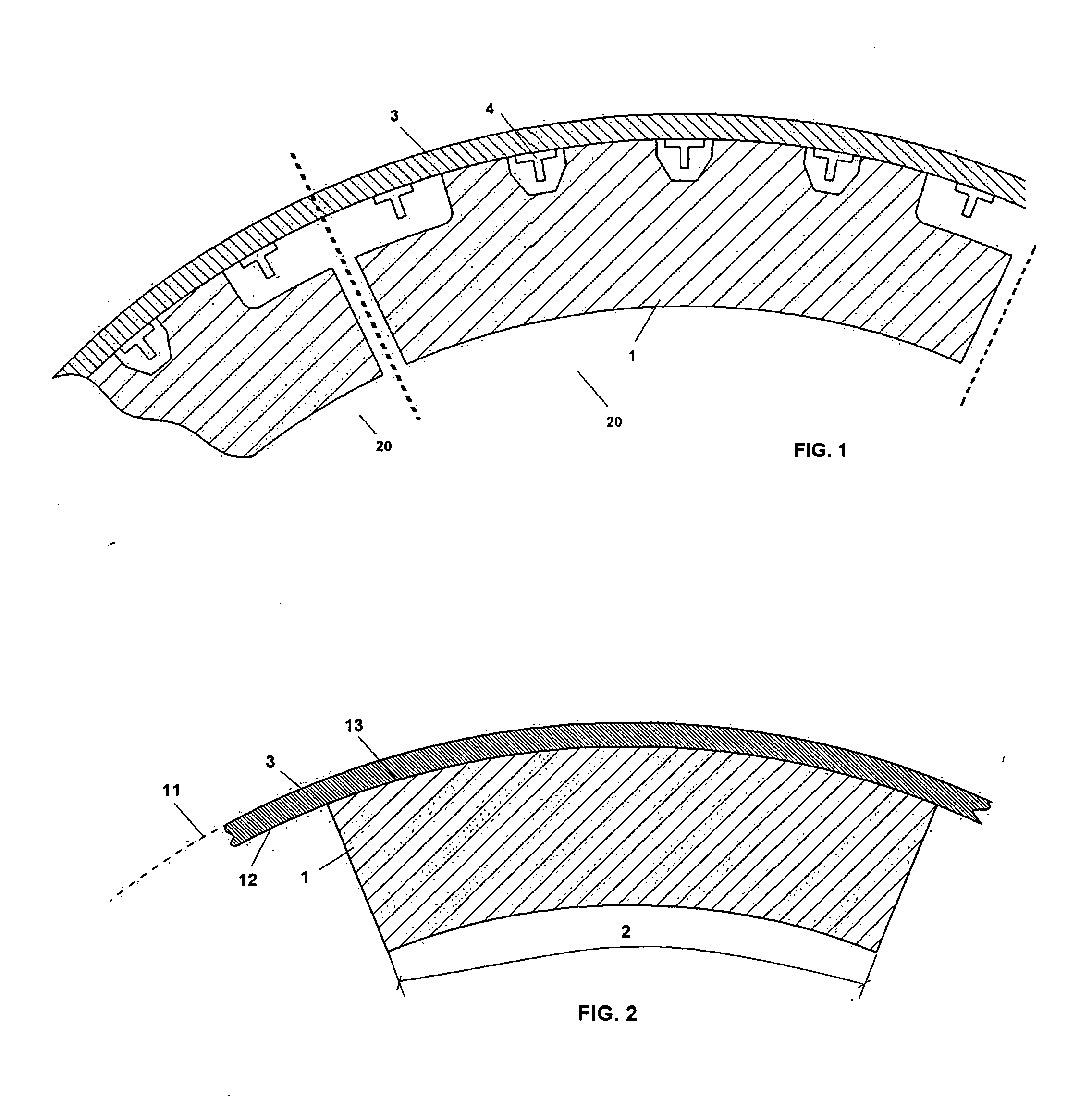
[0007]Thus, according to a first aspect, the invention refers to a new design of an aircraft frame or frames made of composite material, those frames being made in partitions or segments with a determined length, which will be arranged on the interior of the skin that forms the aircraft fuselage. The fuselage will be integrally manufactured in a single piece (called full-barrel or one-shot fuselage). This fuselage may comprise integrated stringers from the same manufacturing process of the aforementioned fuselage. The length of the partitions or segments of the frames will be the maximum possible (which will lead to the minimum number of partitions per diameter of fuselage section), so that the maximum gap between these frame segments and the skin, with this gap being measured from the interior of the skin, allows the use of a liquid sealant for joining the frame segment to the skin. The use of this type of sealant simplifies the operations and decreases the assembly times, which allows recurring costs to decrease in this regard. The maximum length of the frame segments will be calculated based upon the manufacturing limitations given by the manufacturing tolerances of the skin and of the same frame segments.

Problems solved by technology

However, this procedure forces a very high number of segments or partitions of the frames, which involves also having to use a large number of joining parts between the frames and the skin that make up the fuselage.
This causes the procedure of assembling the frames to be very long and expensive, using a large amount of assembly labor.

Method used


Image

  • Aircraft frame and method for obtaining the same
  • Aircraft frame and method for obtaining the same
  • Aircraft frame and method for obtaining the same

Examples


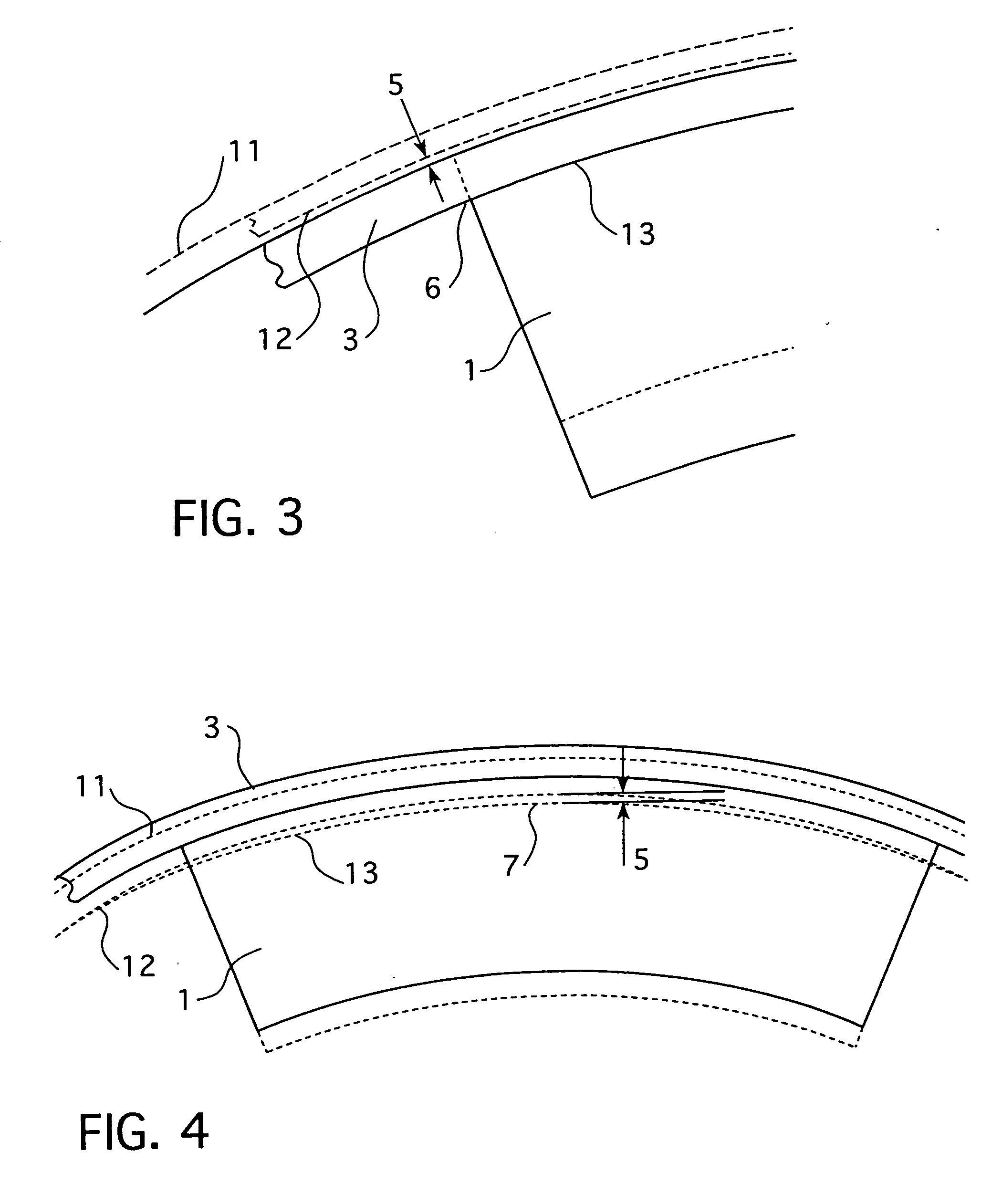
case 1 (fig.3) : [ 0042 ] skin 3 is at its maximum size , since the aerodynamic tolerance is at its maximum (effective external value 11 is the maximum) and its thickness tolerance at its minimum (effective internal value 12 is the maximum) ; [ 0043 ] frame section 1 is at its minimum size , since the manufacturing tolerance of the same is the minimum (effective external value 13 is the minimum) ; [ 0044 ] under the above conditions , the maximum gap 5 between the skin 3 and frame section 1 , for the case of cylindrical fuselage , appears close to the ends 6 of the frame section 1 (fig.3)

[0041]Case 1 (FIG. 3):[0042]skin 3 is at its maximum size, since the aerodynamic tolerance is at its maximum (effective external value 11 is the maximum) and its thickness tolerance at its minimum (effective internal value 12 is the maximum);[0043]frame section 1 is at its minimum size, since the manufacturing tolerance of the same is the minimum (effective external value 13 is the minimum);[0044]under the above conditions, the maximum gap 5 between the skin 3 and frame section 1, for the case of cylindrical fuselage, appears close to the ends 6 of the frame section 1 (FIG. 3).

case 2 (fig.4) : [ 0046 ] skin 3 is at its minimum size , since the aerodynamic tolerance of the same is at its minimum (effective external value 11 is the minimum) and its thickness tolerance the maximum (effective internal value 12 is the minimum) ; [ 0047 ] frame section 1 is a maximum size , since the manufacturing tolerance of the same is the maximum (effective external value 13 is the maximum) ; [ 0048 ] under the above conditions , the maximum gap 5 between the skin 3 and frame section 1 , for the case of cylindrical fuselage , appears in an area 7 close to the center of the frame section 1 (fig.4)

[0045]Case 2 (FIG. 4):[0046]skin 3 is at its minimum size, since the aerodynamic tolerance of the same is at its minimum (effective external value 11 is the minimum) and its thickness tolerance the maximum (effective internal value 12 is the minimum);[0047]frame section 1 is a maximum size, since the manufacturing tolerance of the same is the maximum (effective external value 13 is the maximum);[0048]under the above conditions, the maximum gap 5 between the skin 3 and frame section 1, for the case of cylindrical fuselage, appears in an area 7 close to the center of the frame section 1 (FIG. 4).

[0049]Therefore, based upon cases 1 and 2 mentioned above, the maximum gap 5 is systematically obtained for each possible frame section 1, as per the invention. Once the areas are known in which the gap between skin 3 and the frame segments 1 is the maximum and lower than the application limit of the defined liquid sealant, and in accordance with the remaining stated considerations, the frame ...


PUM

PropertyMeasurementUnit
lengthaaaaaaaaaa
thicknessaaaaaaaaaa
thickness toleranceaaaaaaaaaa

Abstract

An aircraft frame and a method for obtaining an aircraft frame, which frame is made of composite material, and which frame comprises several partitions (20) that form, when joined, the aforementioned frame in its entirety, with these partitions (20) comprising sections (1) with a length (2), and sections (1) that are being arranged on the inside of the skin (3) that forms the fuselage of the aircraft. This fuselage is integrally embodied in a single piece, with the length (2) of the sections (1) being the maximum possible, in such a way that the maximum separation (5) between the frame section (1) and the skin (3), with the separation (5) being measured by the inside of the aforementioned skin (3), is lower than the limit value permitted for the use of a liquid sealant.

Description

FIELD OF THE INVENTION[0001]This invention refers to a new design of aircraft frames in a composite material, specifically for fuselages integrated into a single piece, as well as to a method for obtaining them.BACKGROUND OF THE INVENTION[0002]The fuselage is the main assembly of an aircraft, given that the remaining elements that make up the aircraft are directly or indirectly joined to it. The skin of the fuselage is what gives it its shape, which varies with the main mission that the aircraft will have.[0003]In addition to the skin (the one being considered is CFRP—Carbon Fiber Reinforced Plastic), the fuselage of an aircraft comprises some elements in the shape of a perpendicular framework with respect to the lengthwise axis of the aircraft, called frames (made of CFRP or metal, in the shape of a C, Z, etc.), which are responsible for giving shape and rigidity to the fuselage structure, with these frames being located at given intervals on the inside of the aircraft fuselage. In...

Claims


Application Information

Patent Timeline
Patent Type & Authority Applications(United States)
IPC IPC(8): B64C1/06B23P17/00
CPCB64C1/061B64C1/10Y10T29/4978G06F17/5095B64F5/0009B64F5/10B64F5/00G06F30/15
Inventor LOPEZ, JOSE MARIA PINAVILLARES, ENRIQUE VERA
Owner AIRBUS OPERATIONS SL
Learn More