Conventional filters that achieve high OD values at certain wavelengths or over a range of wavelengths may not necessarily also achieve
high transmission (in excess of 50%, for example) at any other wavelengths, or over other ranges of wavelengths.
Mechanical means to perform filter swapping are known, such as the use of filter wheels, but these are conventionally large, relatively slow (i.e., minimum switching times are conventionally 50 to 100 ms), and permit only a limited number of filters (e.g., conventional wheels contain from 4 to 12 slots for such fixed filters).
Thus, conventional filter systems that can benefit from the use of thin-film filters and also benefit from the availability of variable, or dynamic, spectral characteristics will have limited application as a result of the size, speed, and filtering function flexibility characteristics discussed above.
However, gratings do not offer very good spectral discrimination.
For example, spectral edges are conventionally not highly sloped and out-of-band blocking is conventionally poor.
Moreover, concatenating
multiple diffraction grating spectrometers together in order to address some of these deficiencies tends not to completely alleviate the poor out-of-band blocking, reduces the overall transmission, and further makes the instrument very large.
Further still, at least one spatial dimension is conventionally required for spreading out light rays in a wavelength-
dependent manner for
grating-based systems, and thus it is not possible to measure a two-dimensional imaging beam directly (at one instant of time) with a conventional
diffraction grating.
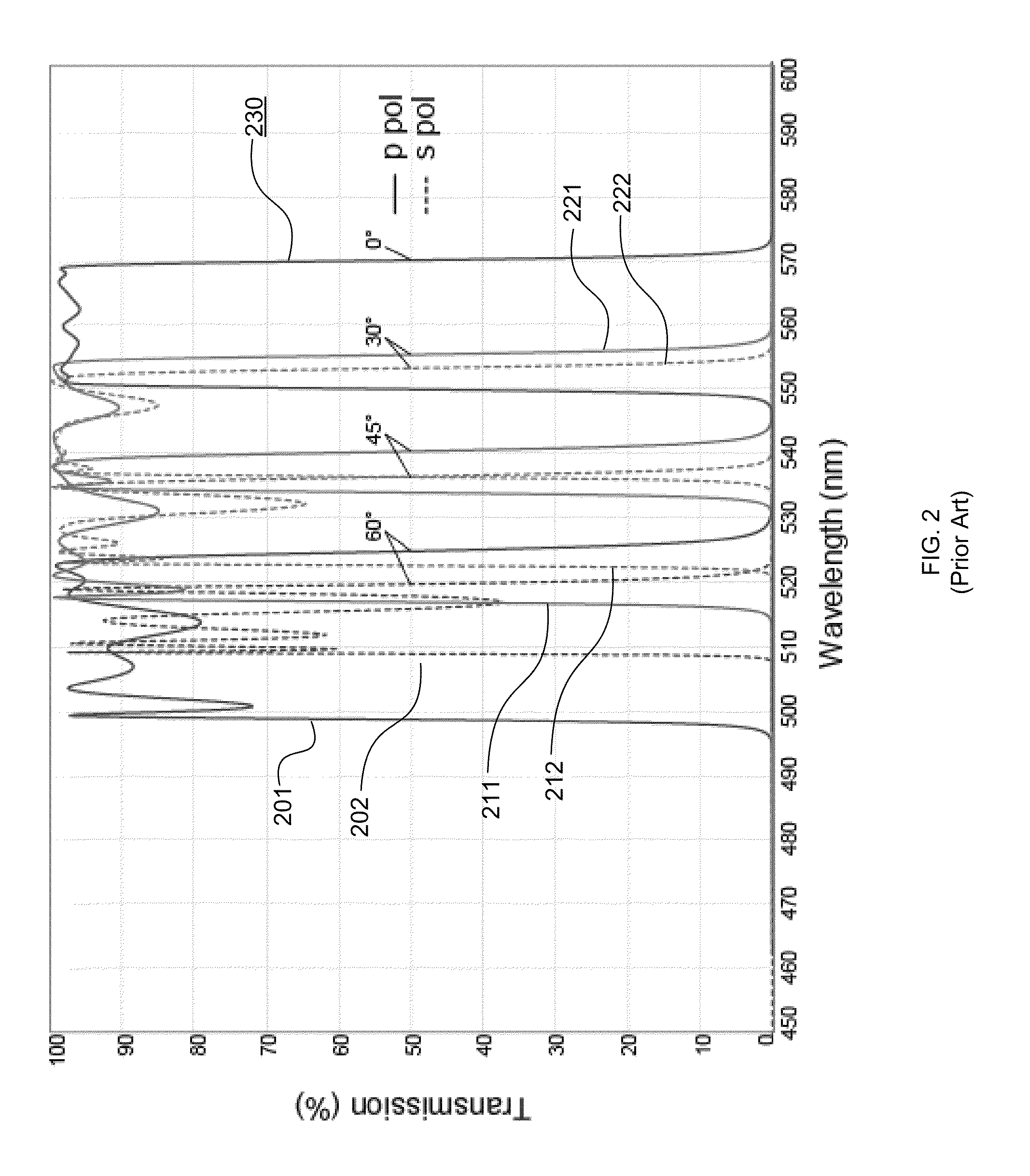
Moreover, the transmission characteristics over the
passband region become increasingly distorted (i.e., exhibit a larger range of variability) at higher AOI.
All of these characteristics conventionally result in an increasingly distorted spectrum at higher AOI, thus reducing the useful tuning range of such a conventional filter.
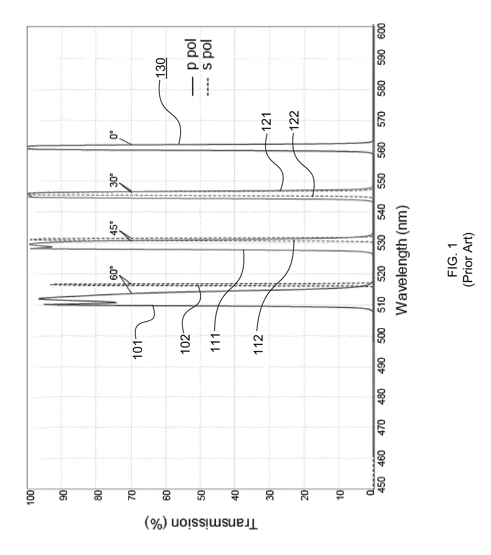
One limitation with such a combination of edge filters, however, is that conventional edge filters exhibit polarization splitting when operated at a non-zero
angle of incidence.
This difference in shift ultimately offsets the filter spectra corresponding to these differing polarizations, resulting in polarization splitting.
However, in the context of edge filters and beamsplitter optical filters, polarization splitting severely limits the edge steepness of light having average polarization.
However, this method has significant limitations when used to create dichroic filters.
It has been shown that decreasing stopband bandwidth can result in a corresponding decrease in polarization splitting.
However, while this method is effective, small mismatch always results in a filter having a narrow blocking region and lower blocking level, which is often not acceptable.
As a result, the performance of a traditional
dichroic filter based on a second order stopband is typically limited by the maximum
coating thickness allowed by the manufacturing process.
Higher-order stopbands are one reason why it is difficult to achieve
high transmission at wavelengths shorter than those over which high blocking occurs.
Each “stage” of this filter produces a sinusoidal variation of transmission as a function of wavelength, and the combination of many stages each producing a sinusoidal
transmission curve with a different frequency results in constructive interference of the overall transmission characteristic at just one wavelength: the filter passband.
The most significant disadvantages include poor edge steepness and out-of-band blocking, lack of adjustable bandwidth, and very small apertures (typically 3 to 10 mm at most), which limits the usefulness for imaging applications.
In addition, because light is always incident at or near 0 degrees AOI they can be polarization insensitive.
Disadvantages include poorer spectral performance (edge steepness) due to the variation of the
spectral properties across a non-zero width
optical beam, and slow tuning speed due to the need to translate the filters mechanically.

