Firing Rate Reduction System for an Automatic Firearm

a technology of automatic firearms and reduction systems, which is applied in the direction of weapons, firing/trigger mechanisms, weapon components, etc., can solve the problems of reducing accuracy, reducing firing rate, and heat the rifle, so as to improve the firing rate and reduce the effect of firing ra

Active Publication Date: 2011-07-21
SY FERDINAND S
View PDF10 Cites 8 Cited by
  • Summary
  • Abstract
  • Description
  • Claims
  • Application Information

AI Technical Summary

Benefits of technology

[0007]In view of the foregoing disadvantages inherent in the known types of rate reduction systems this invention provides an improved firing rate reducer. As such, the present invention's general purpose is to provide a new and improved rate reducer that will be effective, easily manufactured and easily installed with no alteration of the weapon or its systems.
[0008]In practice, the rate reducer according to the present invention utilizes a slidable sear disconnector that is independent of the bolt carrier. The independence of the disconnector causes it to lag behind the bolt carrier as the rifle completes its firing cycle. The lag increases cyclic time and thereby reduces the rate of fire. The present invention also features a modified bolt carrier that is more conducive to assembly with the rate reduction system and a simplified sear disconnector.

Problems solved by technology

One of the difficulties with automatic firearms is a tendency of firing rate to be too rapid for the user or for the mechanical limits of the weapon.
Firing numerous rounds of ammunition from a rifle in full automatic firing mode tends to over heat the rifle and reduce accuracy by affecting the control of the user and the mechanics of the rifle itself.
As a result, there is a greater risk of stray bullets, causing an increased risk of serious physical injury and property damage and even an increased risk of mechanical malfunction.
They range from counter balance, hydraulic, and pneumatic systems, altering buffering capabilities of the rifle, and complicated electronic firing systems.
However, all of these prior art systems require significant modification to a rifle, some are effective with only certain kinds and shapes of ammunition, the electronic system requires additional wiring, controls and batteries, all of which can fail and in most cases require significant cost to manufacture and install.
However, the system did require time for complicated assembly of numerous parts for installation.

Method used


Image

  • Firing Rate Reduction System for an Automatic Firearm
  • Firing Rate Reduction System for an Automatic Firearm
  • Firing Rate Reduction System for an Automatic Firearm

Examples


Embodiment Construction

[0026]With reference now to the drawings, the preferred embodiment of the firing rate reduction system is herein described. It should be noted that the articles “a”, “an” and “the”, as used in this specification, include plural referents unless the content clearly dictates otherwise.

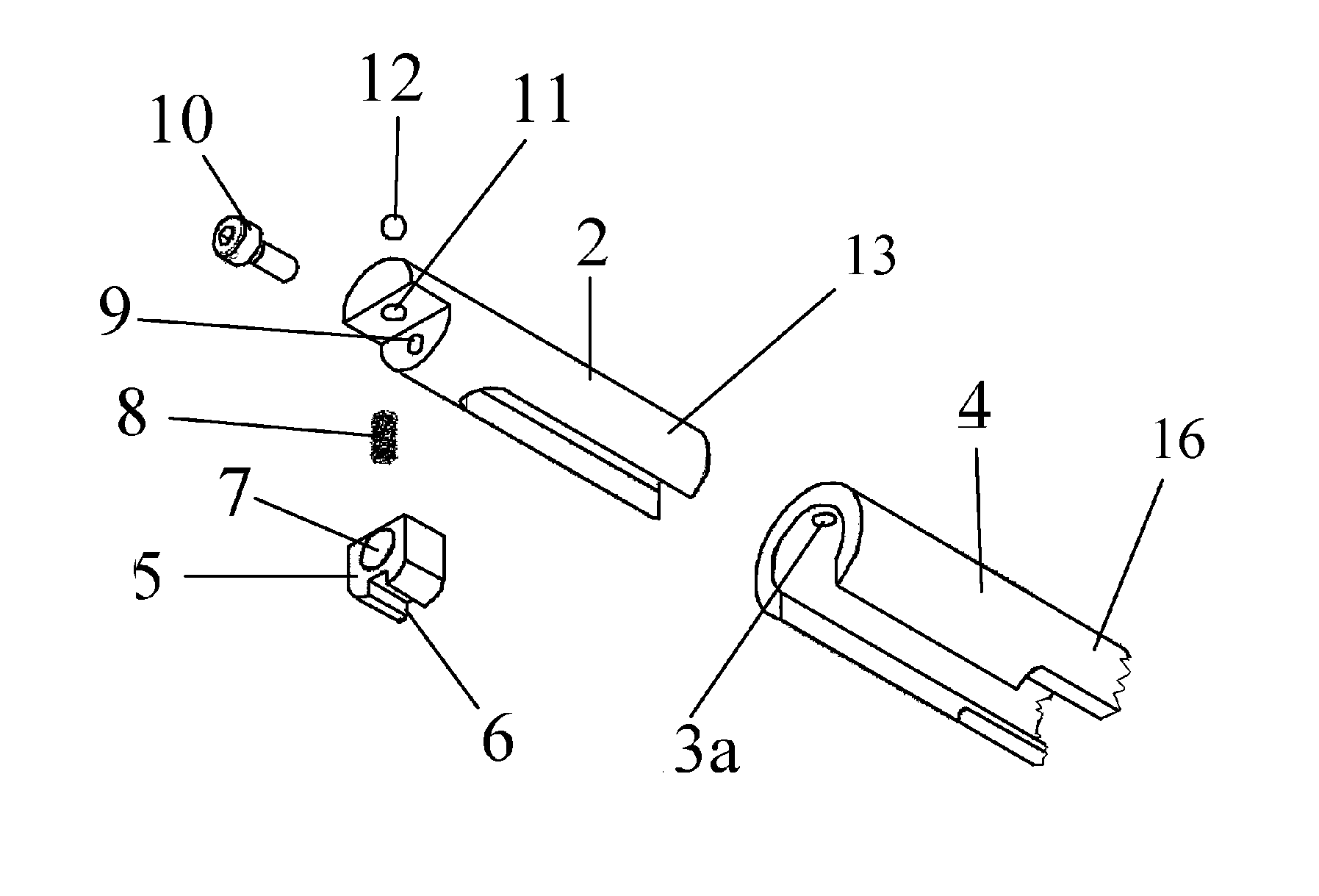
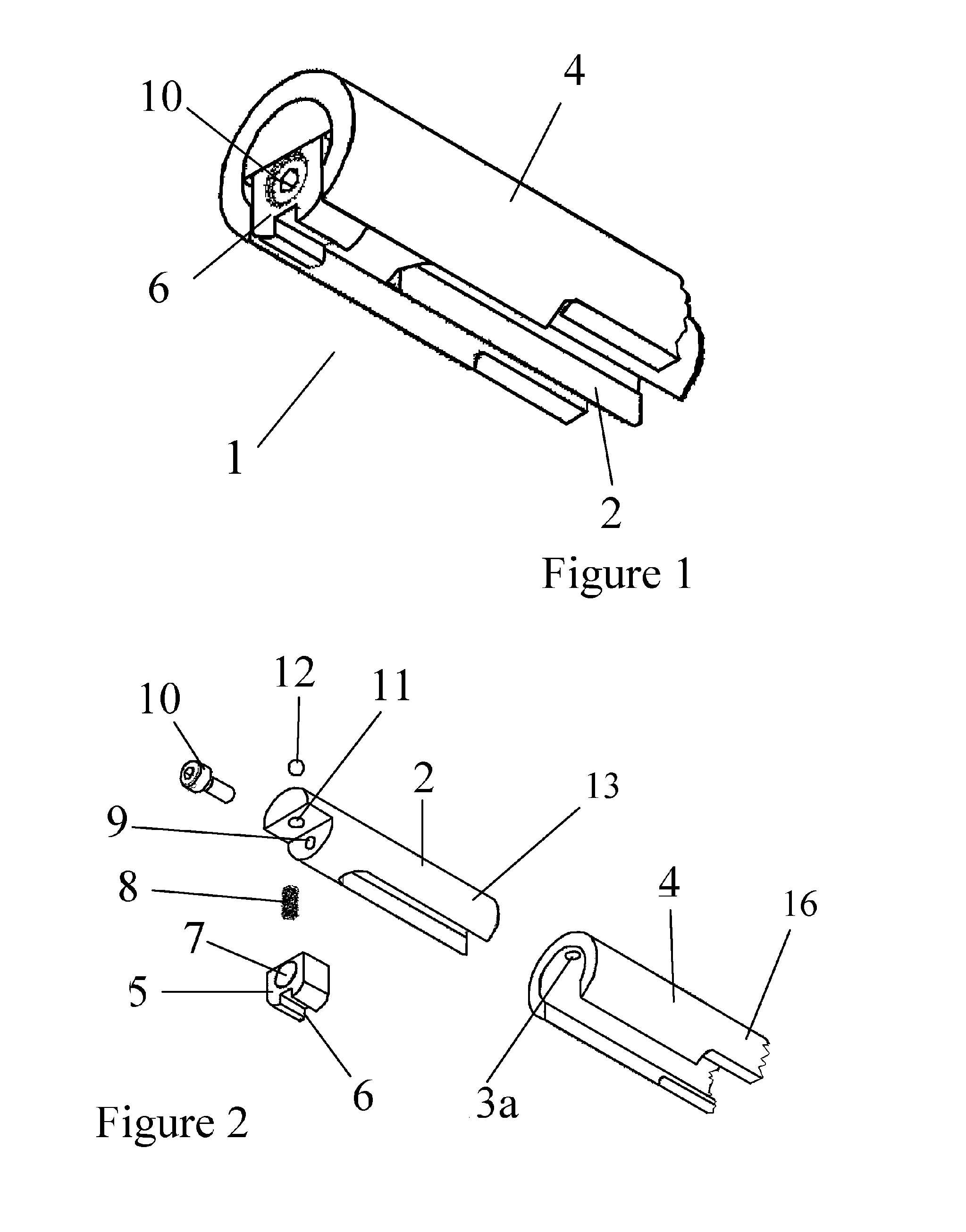
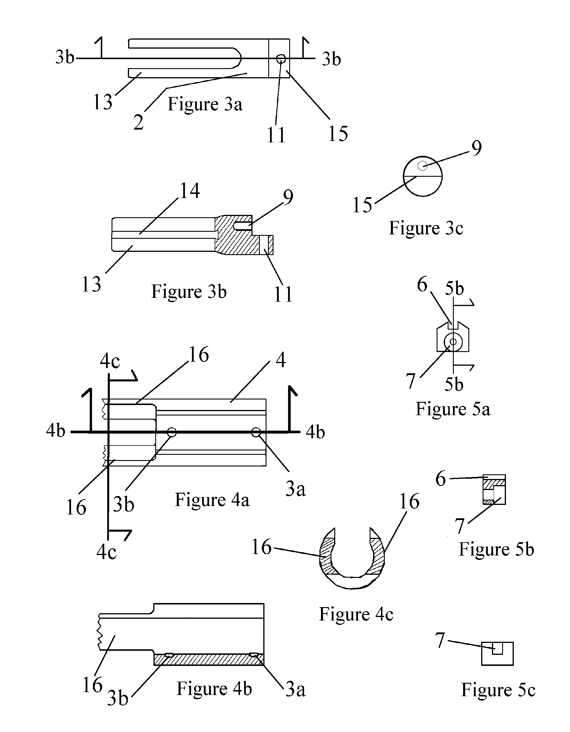
[0027]Referring to FIG. 1, the system 1 comprises a modified, generally tubular bolt carrier 4, the rear of which is shown, with a sideable disconnector body 2 coaxially positioned within. On one end of disconnector body is sear striker 5 fastened with bolt 10. Additional parts are disclosed in FIGS. 2, 3a-3c, 4a-4c, and 5a-5c. As can be seen in FIG. 2, carrier body 4 contains 2 detents 3a and 3b, which interface with ball bearing 12 on disconnector body 2. Ball bearing 12 is inserted in channel 11 of disconnector body 2 and biased by spring 8 within channel 11. Sear striker 5 contains spring 8 in channel 11 when it is connected to body 2 by bolt 10 inserted through bores 7, in the sear striker 5, and 9,...


PUM


Abstract

The present invention is a firing rate reduction system utilizing a slideable, independent sear disconnector. A straight channel, terminating at the rear end of the bolt carrier, for disconnector movement is created in the bolt carrier. Detents are provided to arrest movement at foreword and rearward limits. The force of inertia moves the independent disconnector into these extreme positions and creates a delay in firing time as additional time is required for the independent disconnector to reach final position.

Description

CROSS-REFERENCES TO RELATED APPLICATIONS[0001]The present Application is a non-provisional perfection of prior Provisional Application No. 60 / 593,992, filed Mar. 2, 2005.FIELD OF THE INVENTION[0002]The present invention relates to the filed of firearms and more particularly relates to the field of firing rate reduction systems for automatic firearms.BACKGROUND OF THE INVENTION[0003]One of the difficulties with automatic firearms is a tendency of firing rate to be too rapid for the user or for the mechanical limits of the weapon. Firing numerous rounds of ammunition from a rifle in full automatic firing mode tends to over heat the rifle and reduce accuracy by affecting the control of the user and the mechanics of the rifle itself. As a result, there is a greater risk of stray bullets, causing an increased risk of serious physical injury and property damage and even an increased risk of mechanical malfunction. However, the benefits of an automatic firing mode, i.e. not having to pull ...

Claims


Application Information

Patent Timeline
Patent Type & Authority Applications(United States)
IPC IPC(8): F41A19/67
CPCF41A19/04
Inventor SY, FERDINAND S.
Owner SY FERDINAND S
Why Eureka
Try Eureka