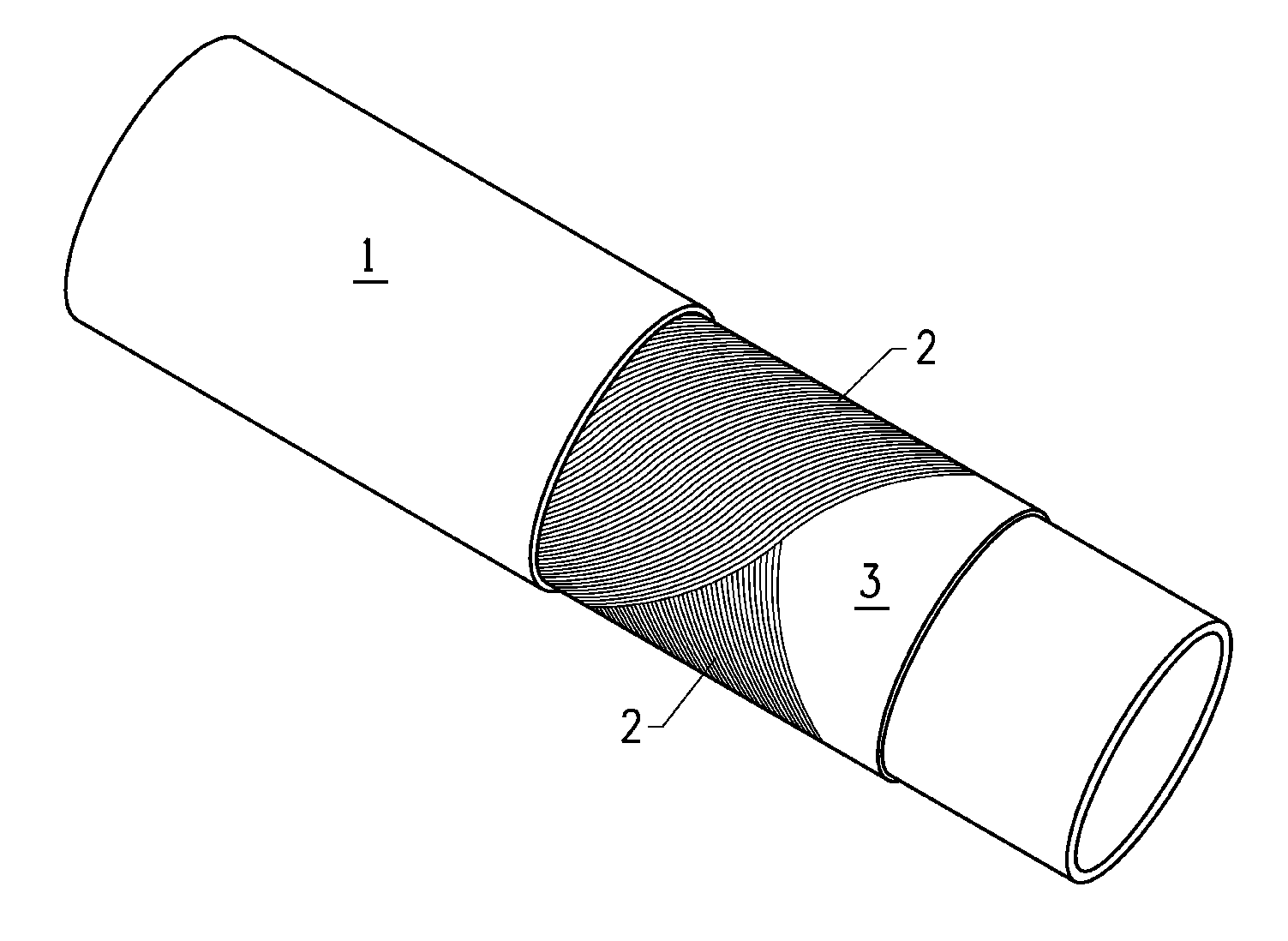
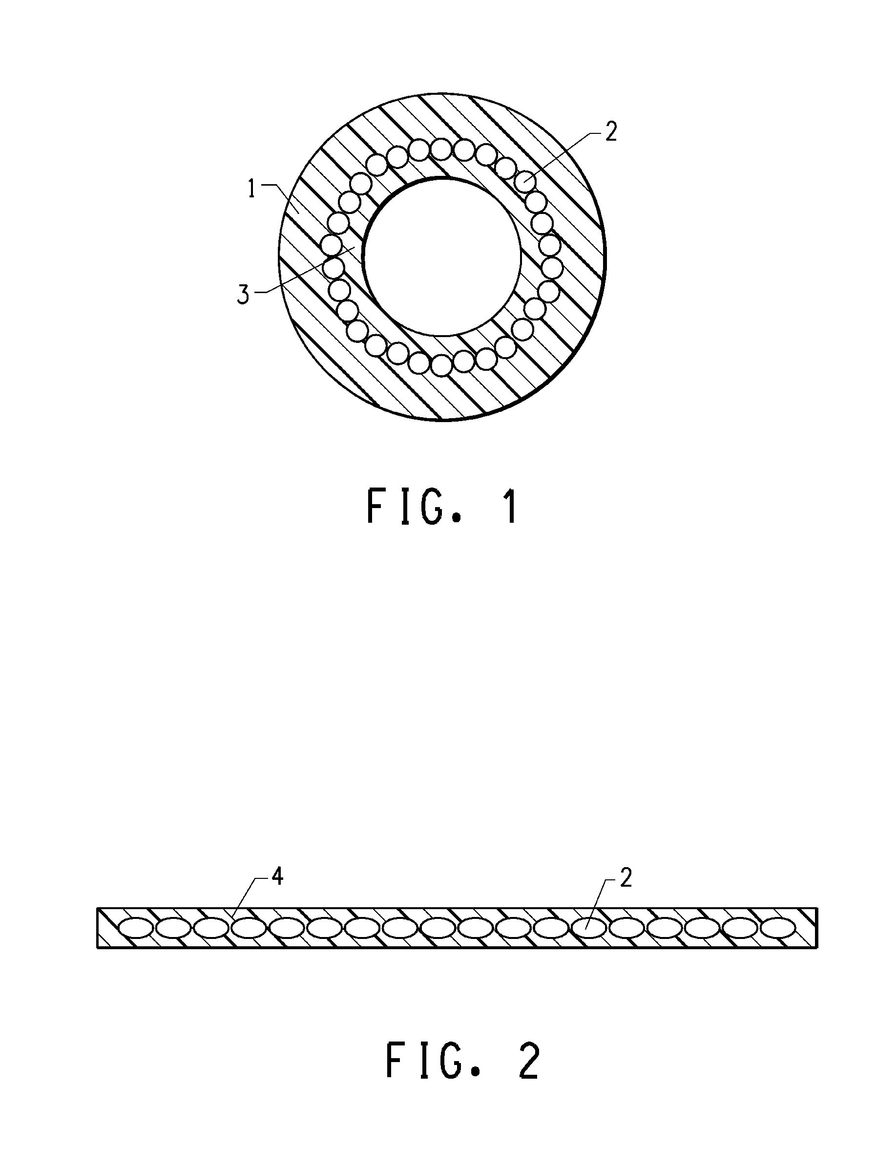
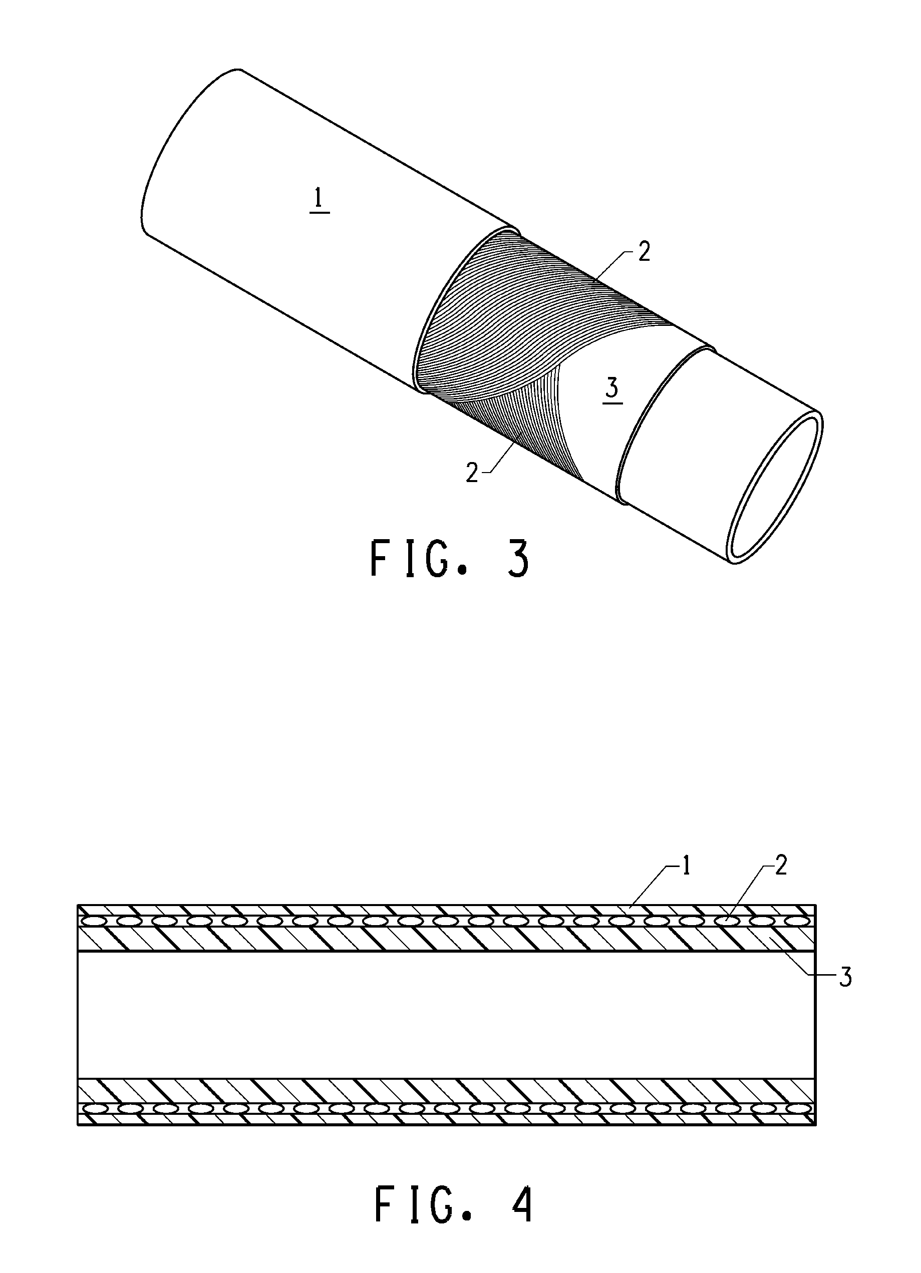
Fiber-reinforced thermoplastic pipe
a thermoplastic pipe and fiber technology, applied in the direction of layered products, mechanical equipment, chemistry equipment and processes, etc., can solve the problems of affecting the cost of their installation and service life, affecting the strength loss of fibers, and being difficult to control, so as to achieve high strength
- Summary
- Abstract
- Description
- Claims
- Application Information
AI Technical Summary
Benefits of technology
Problems solved by technology
Method used
Image

Examples
example 1
[0063]Kevlar® 3000 denier fiber (purchased from DuPont of the United States) is twisted in the Z direction at 80 twists per meter, then three strands of the said twisted fiber are stranded again and twisted in the S direction at 50 twists per meter. The properly twisted cord is marked as Kevlar® 3000×1×3. Then the tape is woven with the said cord on a weaving machine, and the tape is 190 mm in width, warp-wise there are 158 Kevlar® 3000×1×3 twisted cords, while weft-wise there is 600 denier polyester fiber 5 filaments / 10 mm in density. The schematic diagram of the unidirectional tape made is as shown in FIG. 5.
[0064]The unidirectional reinforcing tape obtained goes between two heater plates at 130° C. or so to set the weft-wise polyethylene fiber, and the unidirectional reinforcing tape set is coiled to become a plate to be used.
[0065]The high density polyethylene inner tube (the inner tube diameter is 101 mm, and the inner tube wall thickness is 5 mm) is extruded at 150° C. on an i...
example 2
[0068]Kevlar® 3000 denier fiber (purchased from Du Pont of the United States) is twisted in the Z direction at 80 twists per meter, and the twist factor is 1.5. Then three strands of the said twisted fiber are stranded again and twisted in the S direction at 50 twists per meter, and the twist factor is the S direction is 1.65. The properly twisted cord is marked as Kevlar® 3000×1×3. Then the tape is woven with the said cord on a weaving machine, and the tape is 95 mm in width, warp-wise there are 79 Kevlar® 3000×1×3 twisted cords, while weft-wise there is 600 denier polyester fiber 5 filaments / 10 mm in density. The schematic diagram of the unidirectional tape made is as shown in FIG. 5.
[0069]The unidirectional reinforcing tape obtained goes between two heater plates at 130° C. or so to set the weft-wise polyethylene fiber, and the unidirectional reinforcing tape set is coiled to become a plate to be used.
[0070]The high density polyethylene inner tube (the inner tube diameter is 101 ...
example 3
[0073]Kevlar® 3000 denier fiber (purchased from DuPont of the United States) is twisted in the Z direction at 80 twists per meter, and the twist factor is 1.5. Then three strands of the said twisted fiber are stranded again and twisted in the S direction at 50 twists per meter, and the twist factor in the S direction is 1.65. The properly twisted cord is marked as Kevlar® 3000×1×3. Then the tape is woven with the said cord on a weaving machine, and the tape is 125 mm in width, warp-wise there are 85 Kevlar® 3000×1×3 twisted cords, while weft-wise there is 600 denier polyester fiber 7 filaments / 10 mm in density. The schematic diagram of the unidirectional tape made is as shown in FIG. 5.
[0074]The unidirectional reinforcing tape obtained goes between two heater plates at 130° C. or so to set the weft-wise polyethylene fiber, and the unidirectional reinforcing tape set is coiled to become a plate to be used.
[0075]The high density polyethylene inner tube (the inner tube diameter is 101 ...
PUM
| Property | Measurement | Unit |
|---|---|---|
| linear density | aaaaa | aaaaa |
| linear density | aaaaa | aaaaa |
| melting point | aaaaa | aaaaa |
Abstract
Description
Claims
Application Information
 - R&D
- Intellectual Property
- Life Sciences
- Materials
- Tech Scout
- Unparalleled Data Quality
- Higher Quality Content
- 60% Fewer Hallucinations
Browse by: Latest US Patents, China's latest patents, Technical Efficacy Thesaurus, Application Domain, Technology Topic, Popular Technical Reports.
© 2025 PatSnap. All rights reserved.Legal|Privacy policy|Modern Slavery Act Transparency Statement|Sitemap|About US| Contact US: help@patsnap.com