Laser dicing apparatus

a laser beam and dicing technology, applied in the direction of stone-like material working apparatus, manufacturing tools, welding/soldering/cutting articles, etc., can solve the problems of insufficient control of crack formation, optical damage to the inside, and crack region

Inactive Publication Date: 2011-07-21
TOSHIBA MASCH CO LTD
View PDF53 Cites 23 Cited by
  • Summary
  • Abstract
  • Description
  • Claims
  • Application Information

AI Technical Summary

Problems solved by technology

According to the method disclosed in Japanese Patent No. 3867107, a pulse laser beam causes optical damage to the inside of an object to be processed, to form a crack region.
However, the conventional method has a problem that a crack is formed at an unexpected site, and the formation of the crack cannot be controlled in an adequate ...

Method used


Image

  • Laser dicing apparatus
  • Laser dicing apparatus
  • Laser dicing apparatus

Examples


Embodiment Construction

[0018]Hereinafter, an embodiment of the present invention will be described with reference to the accompanying drawings.

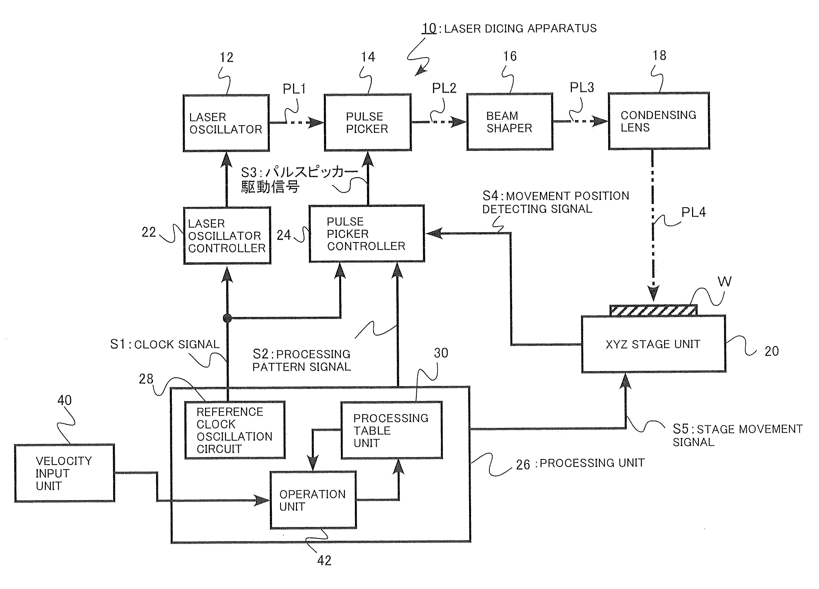
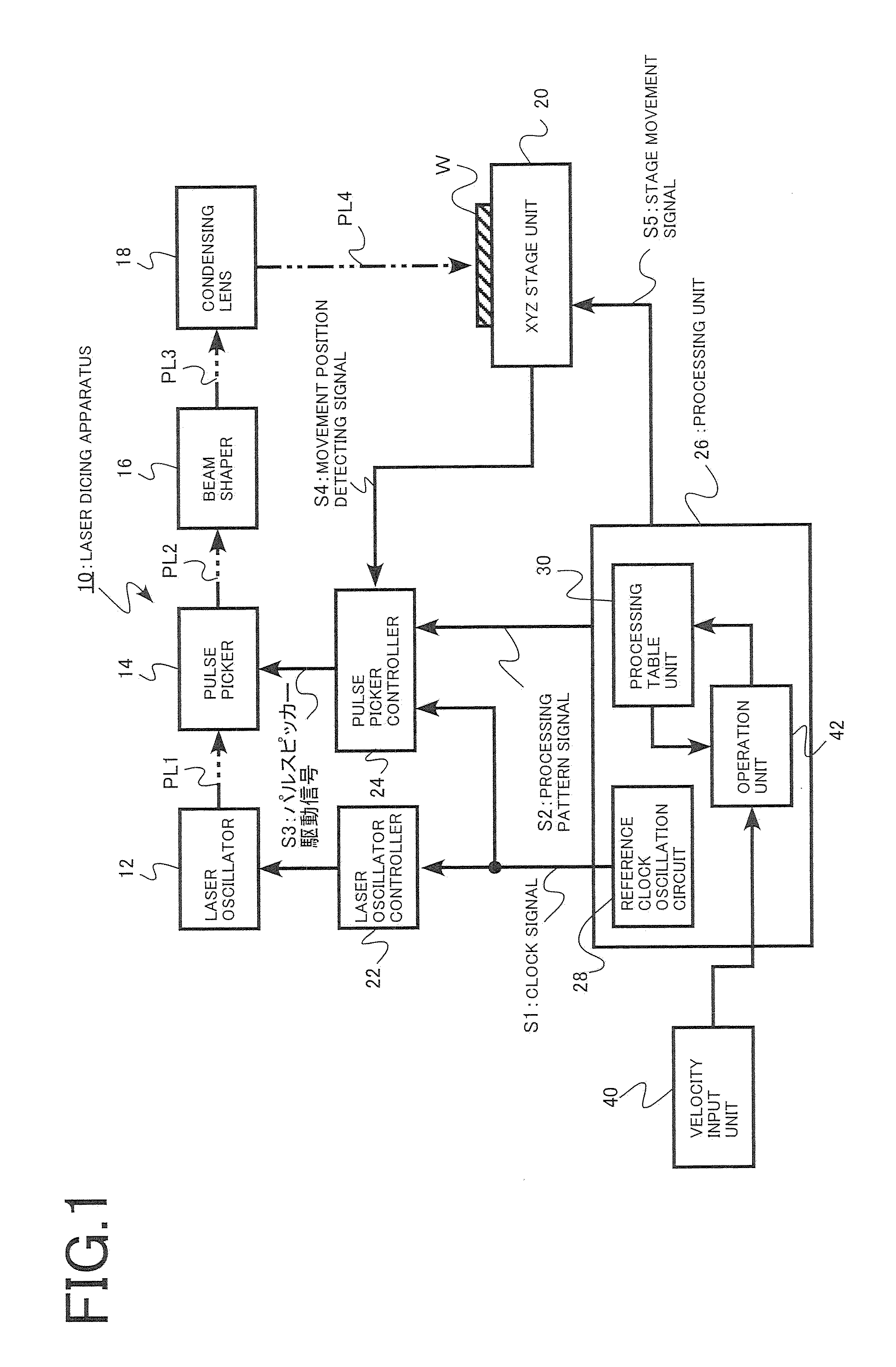
[0019]A laser dicing apparatus of this embodiment includes: a stage on which a substrate to be processed can be mounted; a reference clock oscillation circuit that generates a clock signal; a laser oscillator that emits a pulse laser beam; a laser oscillator controller that synchronizes the pulse laser beam with the clock signal; a pulse picker that switches irradiation and non-irradiation of the pulse laser beam onto the substrate to be processed, the pulse picker being placed in an optical path between the laser oscillator and the stage; and a pulse picker controller that controls pass and interception of the pulse laser beam for each light pulse at the pulse picker in synchronization with the clock signal. The laser dicing apparatus further includes: a processing table unit that stores a processing table in which dicing processing data with respect to a standard...


PUM

PropertyMeasurementUnit
Velocityaaaaaaaaaa

Abstract

A laser dicing device is provided to perform dicing processing that has excellent cutting properties and is stable even when the dicing speed is changed. The laser dicing apparatus includes: a stage; a reference clock oscillation circuit; a laser oscillator that emits a pulse laser beam; a laser oscillator controller that synchronizes the pulse laser beam with the clock signal; a pulse picker that switches irradiation and non-irradiation of the pulse laser beam onto the substrate to be processed; a pulse picker controller that controls pass and interception of the pulse laser beam for each light pulse in synchronization with the clock signal; a processing table unit that stores a processing table in which dicing processing data with respect to a standard relative velocity between the substrate to be processed and the pulse laser beam is written; a velocity input unit that inputs a new set value of a relative velocity; and an operation unit that calculates a new processing table and stores the new processing table into the processing table unit. Based on the new processing table, the pulse picker controller controls pass and interception of the pulse laser beam.

Description

CROSS-REFERENCE TO RELATED APPLICATION[0001]This application is based on and claims priority of Japanese Patent Application (JPA) No. 2010-011348, filed on Jan. 21, 2010, the entire contents of which are incorporated herein by reference.FIELD OF THE INVENTION[0002]The present invention relates to a laser dicing apparatus using a pulse laser beam.BACKGROUND OF THE INVENTION[0003]A method that uses a pulse laser beam in dicing of a semiconductor substrate is disclosed in Japanese Patent No. 3867107. According to the method disclosed in Japanese Patent No. 3867107, a pulse laser beam causes optical damage to the inside of an object to be processed, to form a crack region. The object to be processed is cut on the bases of the crack region.[0004]In the conventional art, formation of the crack region is controlled, with parameters being the energy and spot diameter of the pulse laser beam, and the relative movement velocity between the pulse laser beam and the object to be processed.[0005...

Claims


Application Information

Patent Timeline
IPC IPC(8): B23K26/00B23K26/08B28D5/00
CPCB23K26/0057B23K26/063B23K26/4075B23K26/407B23K26/0861B23K26/40B23K26/0622B23K26/53B23K2103/50B23K26/38
Inventor IDE, MITSUHIROHAYASHI, MAKOTO
Owner TOSHIBA MASCH CO LTD
Why Eureka
Try Eureka