Arrangements and method for measuring an eye movement, particularly a movement of the fundus of the eye

a technology of eye movement and arrangement, applied in the field of arrangement and methods for the (fast) measurement of the movement of the eye, can solve the problems of low effective image refresh rate, measurement can only be taken in a limited motion field, and achieve the limitation of spatial resolution or observed maximum, so as to achieve great spatial measurement accuracy, low cost, and high effective image refresh rate

Active Publication Date: 2011-07-21
CARL ZEISS MEDITEC AG
View PDF13 Cites 10 Cited by
  • Summary
  • Abstract
  • Description
  • Claims
  • Application Information

AI Technical Summary

Benefits of technology

[0008]The invention is based on the task of improving an arrangement and a method of the initially described type in such a way that a higher effective image refresh rate than in prior art is possible with great spatial measurement accuracy and minimal expenditure.

Problems solved by technology

However, the readout of such large images from the camera sensor and the subsequent analysis of, at least, partial image areas take a relatively long time due to the amount of data, resulting only in low, effective image refresh rates, i.e., rates for the recording, including the subsequent analysis, of no more than a few 100 Hz.
However, according to prior art, this can only be achieved through limiting of the spatial resolution or the observed maximum motion field.
The measurement of the movement of the eye fundus, particularly during a treatment of the retina, e.g., a laser coagulation, poses the additional problem that the necessary illumination must only lie within the infrared (IR) wavelength range in order to avoid a glare and therefore a blink reflex, even though the eye fundus is poor in contrast in the IR range.
However, since the eye fundus only exhibits a few larger blood vessels, only a small portion of the eye fundus can be utilized for this type of analysis, hence measurements can only be taken in a limited motion field.
However, they are disadvantageous because an elaborate laser scanner is required.

Method used


Image

  • Arrangements and method for measuring an eye movement, particularly a movement of the fundus of the eye
  • Arrangements and method for measuring an eye movement, particularly a movement of the fundus of the eye
  • Arrangements and method for measuring an eye movement, particularly a movement of the fundus of the eye

Examples


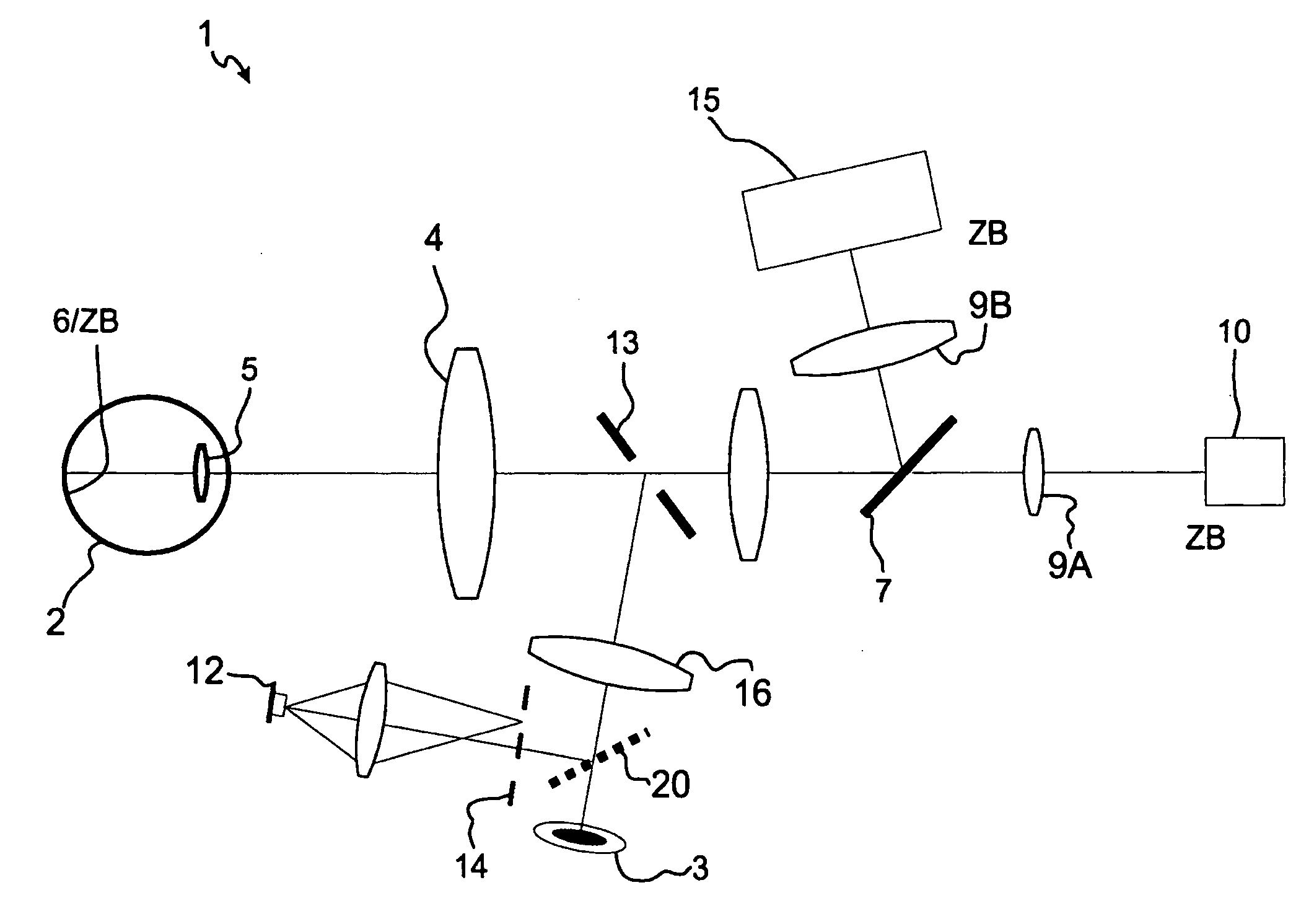
Embodiment Construction

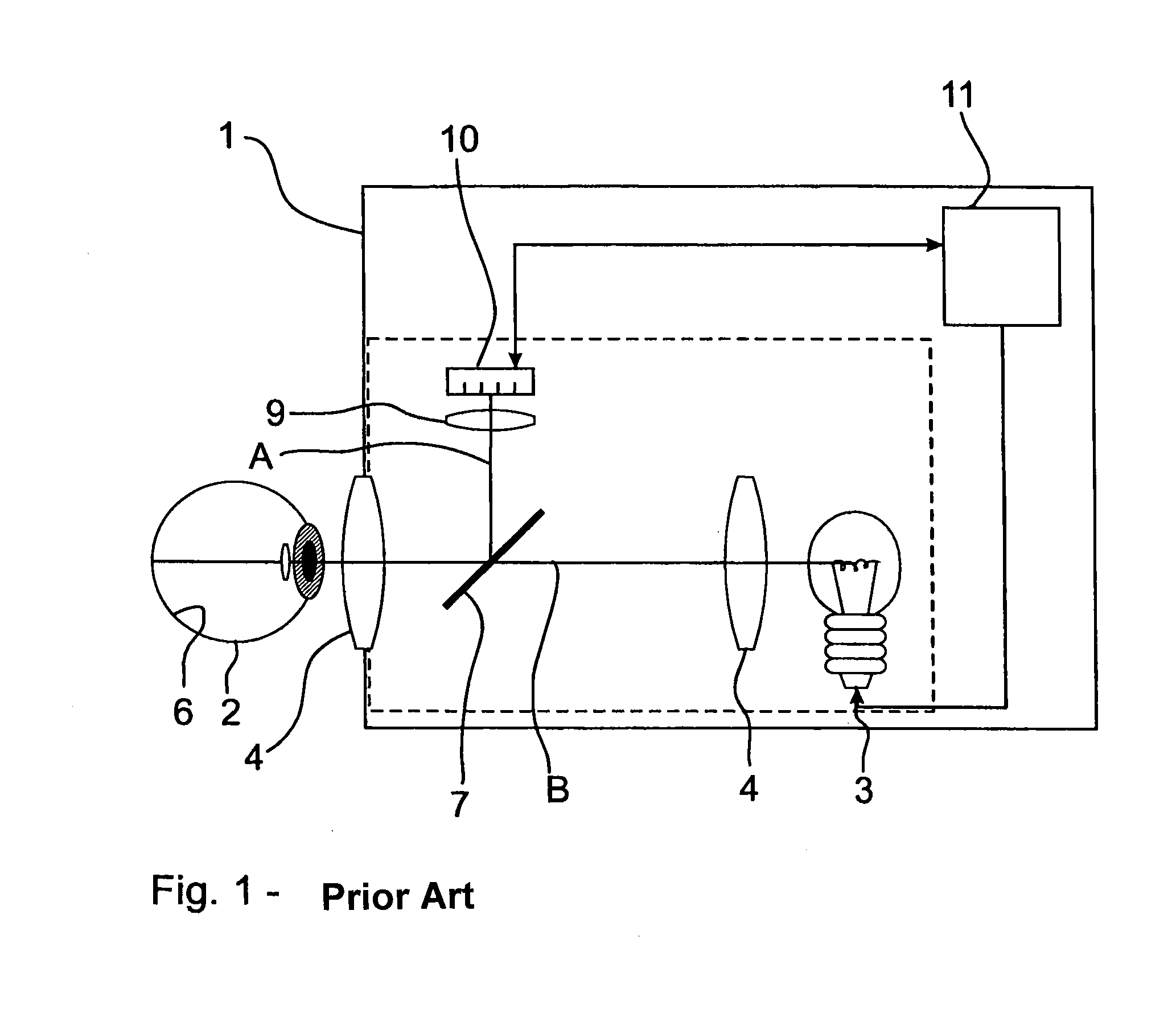
[0044]In all drawings, all corresponding parts bear the same legend.

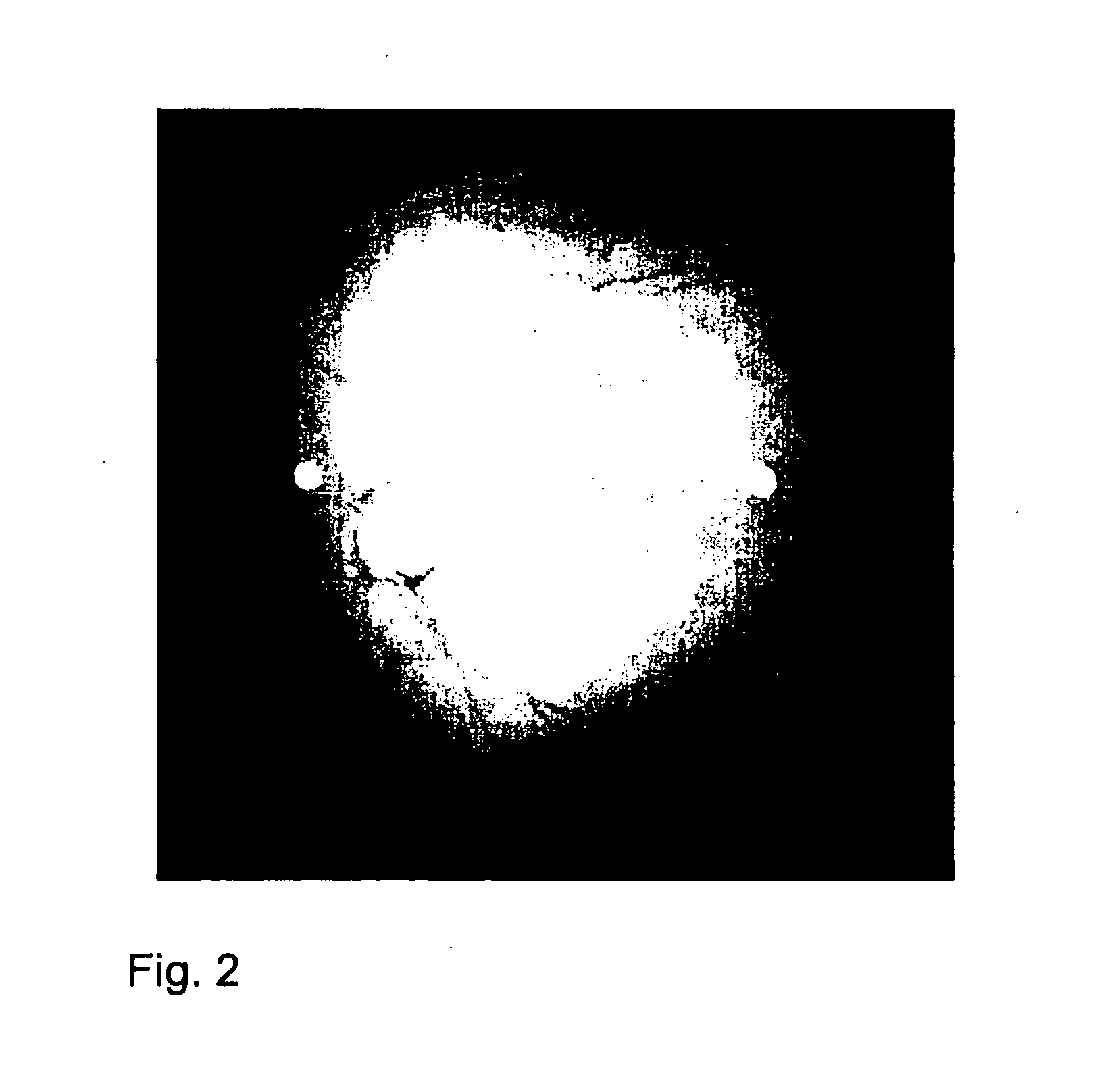
[0045]If a scattering surface, such as paper or a wall, is illuminated with a laser or any other spatially and temporally coherent light source, the light that is backscattered from the surface can interfere in the space, whereby a typical pattern of grainy structures or speckles occurs, which, in accordance with the invention, is termed speckle pattern. A distinction is made between subjective and objective speckles. Subjective speckles occur when the scattering surface is imaged with optics on the camera sensor. The subjective speckles exhibit exactly the same size as the optical resolution of the imaging system. The subsequently registered speckle pattern moves with the shifts of the scattering surface, thus allowing for a quantitative determination of the shift. Objective speckles occur when the camera sensor is positioned without optics in the light backscattered from the sample. Objective speckles react to til...


PUM


Abstract

In addition to a first detector for capturing a potential movement field of the eye in overview images, a second detector is used to capture a particular section of the eye in sectional images. From a displacement between two overview images and an intermediate displacement between two sectional images taken between said overview images, the eye movement is determined by linking said displacements. The sections are preferably illuminated by coherent light such that interfering light diffused on the eye produces a patch pattern. Alternatively, the sclera of the eye is illuminated with coherent light such that light diffused on the sclera produces a patch pattern, of which a particular part is captured using a spatially resolving detector in sectional images, on the basis of which an intermediate displacement is determined.

Description

PRIORITY CLAIM[0001]The present application is a National Phase entry of PCT Application No. PCT / EP2009 / 006816, filed Sep. 22, 2009, which claims priority from German Application Number 102008049881.5, filed Sep. 30, 2008, and German Application Number 102008049846.7, filed Sep. 30, 2008, the disclosures of which are hereby incorporated by reference herein in their entirety.FIELD OF THE INVENTION[0002]The invention relates to arrangements and methods for the (fast) measurement of a movement of a human eye, particularly an eyeground (fundus), by means of a two-dimensional spatially resolving detector for repeated imaging of a potential motion field of the eye in overview images.BACKGROUND[0003]For quite some time, motion tracking arrangements for the measurement and tracking of the eye movement (eye trackers) have been utilized in ophthalmology and other fields of application for, among others, the purpose of research, diagnosis, and therapy. For example, during a treatment of the ey...

Claims


Application Information

Patent Timeline
Patent Type & Authority Applications(United States)
IPC IPC(8): A61B3/113A61B3/14
CPCA61B3/113G02B27/0093A61B3/1225
Inventor BUBLIZT, DANIELRICHTER, STEFAN
Owner CARL ZEISS MEDITEC AG
Why Eureka
Try Eureka