Vertebral pars interarticularis clamp a new spine fixation device, instrumentation, and methodology

Inactive Publication Date: 2011-07-21
SPINECO
View PDF12 Cites 38 Cited by
  • Summary
  • Abstract
  • Description
  • Claims
  • Application Information

AI Technical Summary

Benefits of technology

[0060]Still another and/or alternative non-limiting object of the present invention is the provision of a spinal implant that can permit the ability to control vertebral motion or manipulation.
[0061]Yet another and/or alternative non-limiting object of the present invention is the pro

Problems solved by technology

As such, the spinal implant does not require drilling of insertion holes into the vertebrae, which insertion holes can i) cause damage to the vertebrae (e.g., fracturing and/or splitting of the vertebrae, etc.), and ii) require healing of the

Method used


Image

  • Vertebral pars interarticularis clamp a new spine fixation device, instrumentation, and methodology
  • Vertebral pars interarticularis clamp a new spine fixation device, instrumentation, and methodology
  • Vertebral pars interarticularis clamp a new spine fixation device, instrumentation, and methodology

Examples


Embodiment Construction

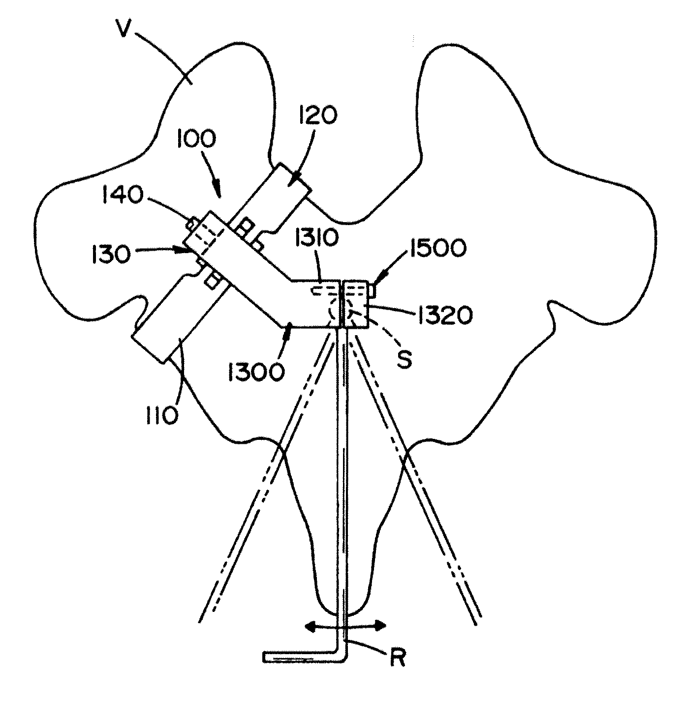
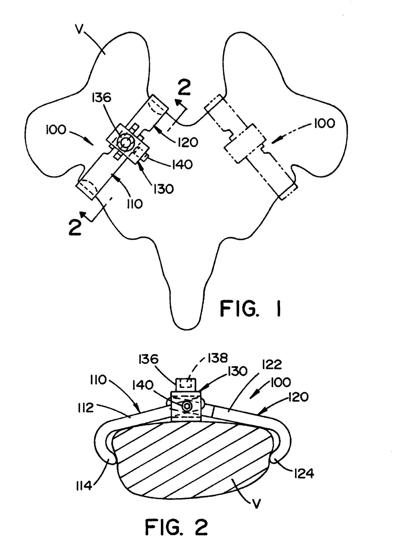
[0082]Referring now to the preferred embodiment of the drawings, wherein the showings are for the purpose of illustrating a preferred embodiment of the invention only and not for the purpose of limiting the invention, FIGS. 1-22 illustrate a spinal implant 100 in accordance with the present invention. As best illustrated in FIG. 1, the spinal implant is designed to be at least partially secured to the posterior elements of a spinal vertebra V. In particular, the spinal implant, as shown in FIG. 1, is secured to the vertebra V within the interval between the superior margin of the lamina of the vertebra and the lateral margin of the pars interarticularis portion of the vertebra. As can be appreciated, the spinal implant can be designed to span the full length of the pars interarticularis, a portion of the pars interarticularis, or connect to more than one vertebra. As best illustrated in FIG. 1, one or more spinal implants 100 can be secured to a vertebra.

[0083]As illustrated in FIGS...


PUM


Abstract

An improved spinal surgical implant used primarily in the posterior aspect of the spinal column for spinal reconstruction; revision surgery; deformity correction; and/or tumor surgery and/or trauma surgery of the cervical, thoracic and/or lumbo-sacral spine.

Description

[0001]The present invention is a continuation-in-part of U.S. patent application Ser. No. 11 / 405,203 filed Apr. 17, 2006, which in turn claims priority on co-pending U.S. Provisional Application Ser. No. 60 / 674,426 filed Apr. 25, 2005, both of which are incorporated herein by reference.[0002]The present invention is directed to implants, more particularly to spinal implants, and even more particularly to a device and method for using a device that is designed to secure to the spinal column.BACKGROUND OF THE INVENTION[0003]The human spine is made up of a column of thirty-three bones and their adjoining structures. The bodies of these vertebrae are connected by anterior and posterior ligaments and by discs of fibrocartilage generally known as intervertebral discs. These discs are positioned between opposite faces of adjacent vertebral bodies. This column of vertebrae and intervertebral discs forms a central axis that supports the head and torso. These vertebrae also enclose an opening...

Claims


Application Information

Patent Timeline
IPC IPC(8): A61B17/70
CPCA61B17/7047
Inventor BISCUP, ROBERT S.LEROUX, CLAYTON G.
Owner SPINECO
Why Eureka
Try Eureka