
Anti-rollback Control System for Motor Vehicles

Inactive Publication Date: 2011-07-21
MARCUS ESSAM TAWFIK
View PDF7 Cites 9 Cited by
  • Summary
  • Abstract
  • Description
  • Claims
  • Application Information

AI Technical Summary

Benefits of technology

[0010]The present invention provides an anti-rollback control system for use in a motor vehicle, to prevent undesired rolling of said vehicle on launching it on an incline, with said anti-rollback control system being simple to design, economic to manufacture and maintain, and having a relatively simple mode of action which makes it less prone to malfunctions during operation.
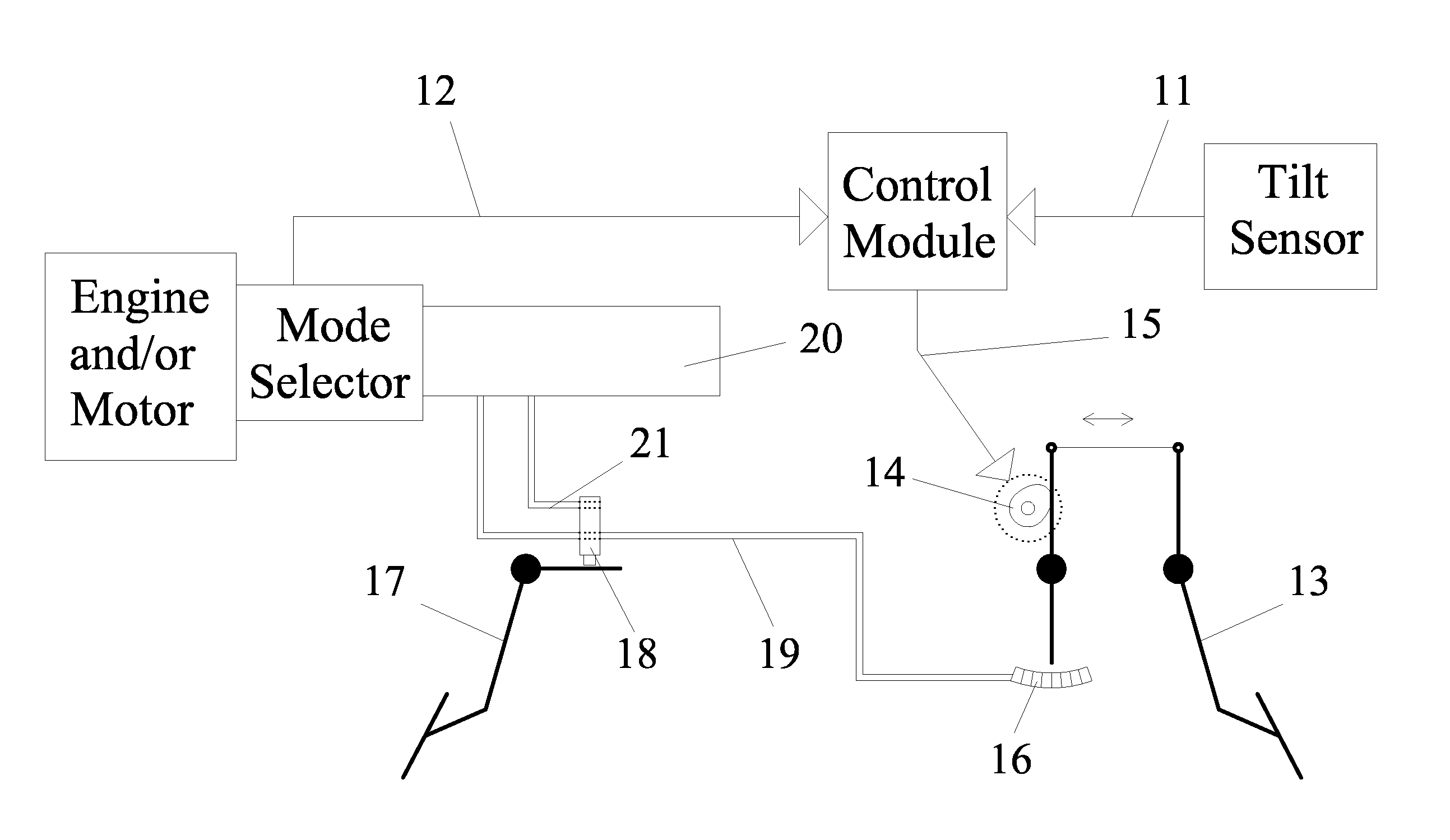
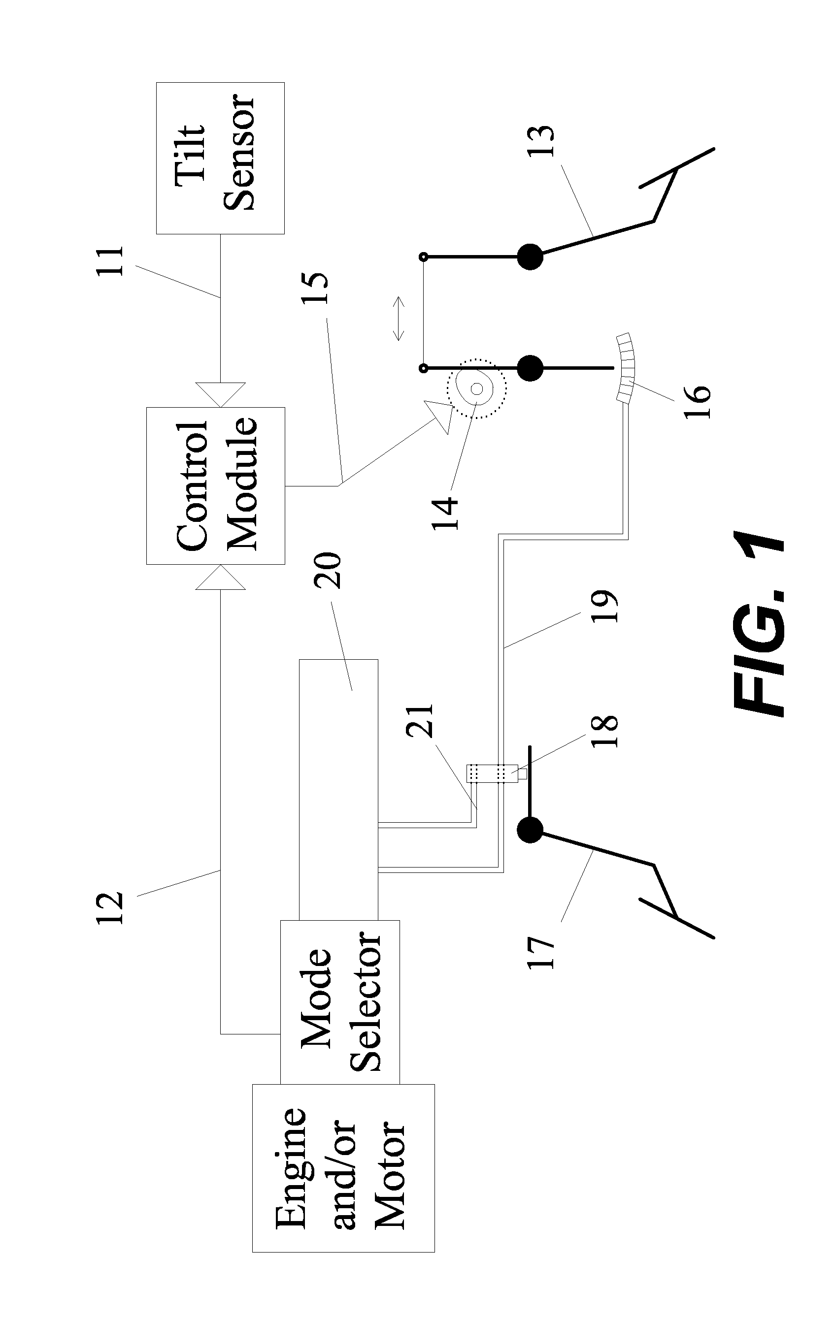
[0012]Accordingly, in a motor vehicle having a powertrain that includes an ICE (internal combustion engine) and / or an electric motor, and an accelerator pedal that is mechanically incorporated with at least one position-sensing electronic device, with the amount of fuel supplied to said ICE and / or the amount of electric power delivered to said electric motor, and hence the amount of mechanical power generated by said powertrain, being a function of the position of at least one movable component of the said at least one position-sensing electronic device, the present invention provides an anti-rollback control system for preventing undesired rolling of said motor vehicle on beginning / resuming the movement of the vehicle after stopping it on an incline.
[0016]In yet another feature, the said anti-rollback control system further comprises a brake pedal actuated device constructed and configured to cause closure of an electrical circuit connected to at least one component of the vehicle's powertrain once the brake pedal reaches a predetermined position, with the said component of the vehicle's powertrain being constructed and configured to cause at least one component of the vehicle's powertrain to move to its idle operating position once the said electrical circuit is closed. In a preferred embodiment, the brake pedal actuated device is an electrical switch constructed and configured to close the said electrical circuit connected to at least one component of the vehicle's powertrain once the brake pedal reaches a predetermined position. In another preferred embodiment, the brake pedal actuated device includes a first brake pedal actuated electrical switch; a second solenoid actuated switch; and a second electrical circuit that connects the first brake pedal actuated electrical switch to the second solenoid actuated switch, with the first brake pedal actuated electrical switch being constructed and configured to close the said second electrical circuit once the brake pedal reaches a predetermined position, and with the second solenoid actuated switch being constructed and configured to close the said electrical circuit connected to at least one component of the vehicle's powertrain once the second electrical circuit is closed. In yet another preferred embodiment, the brake pedal actuated device comprises a position sensor that detects a position of the brake pedal and generates signals accordingly; a control module; and a solenoid actuated switch included within the said electrical circuit, with the said control module being constructed and configured to receive the signals generated by said position sensor, process said received signals, and send instructions to said solenoid actuated switch to close the said electrical circuit connected to at least one component of the vehicle's powertrain once the brake pedal reaches a predetermined position. This feature enables moving at least one component of the vehicle's powertrain to its idle operating position when the vehicle brakes are applied.
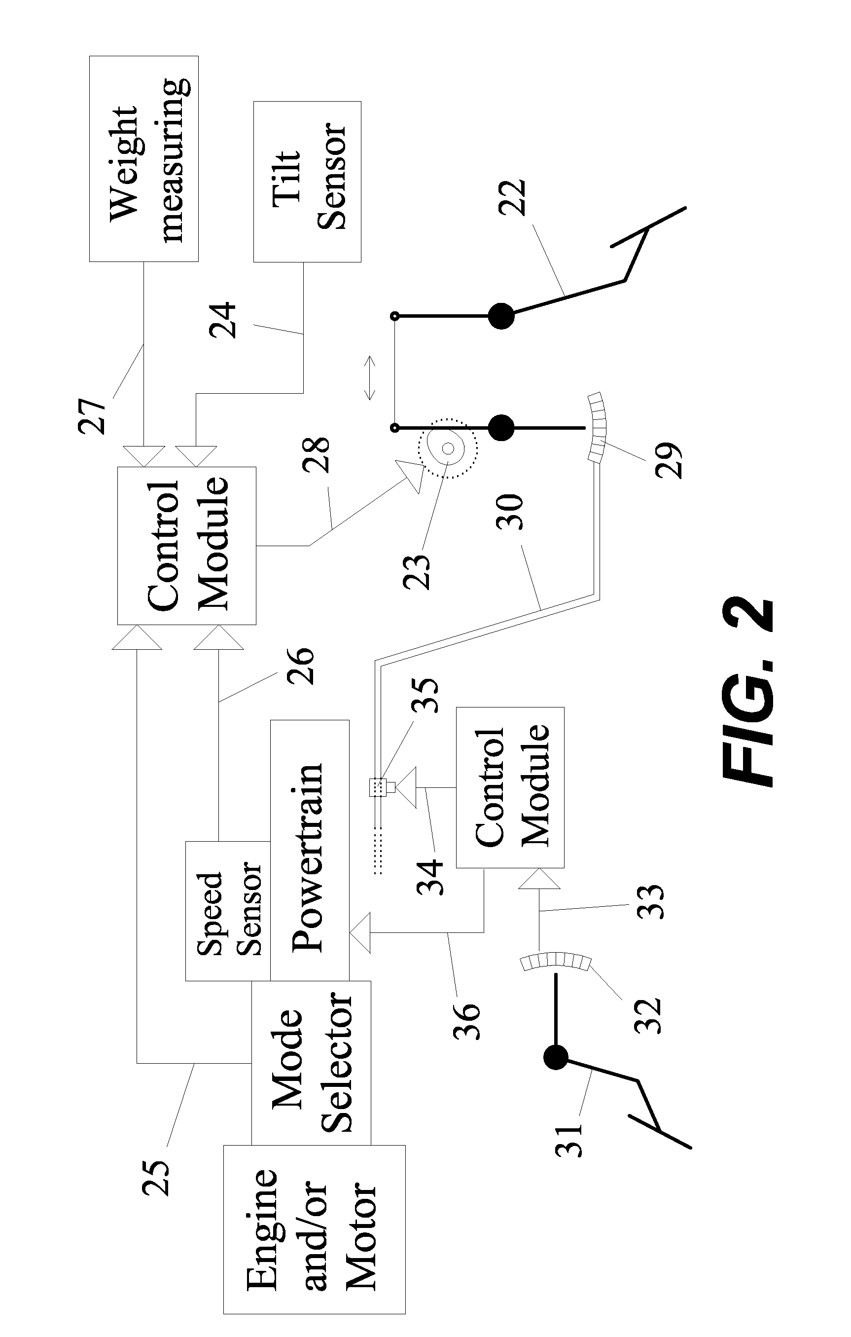
[0017]In another feature, the said anti-rollback control system further comprises a pressure-activated device that detects the hydrostatic pressure of a working fluid within the vehicle's brake system, with said pressure-activated device being constructed and configured to cause closure of an electrical circuit connected to at least one component of the vehicle's powertrain once the hydrostatic pressure within the said brake system reaches a predetermined level, with the said component of the vehicle's powertrain being constructed and configured to cause at least one component of the vehicle's powertrain to move to its idle operating position once the said electrical circuit is closed. In a preferred embodiment, the pressure-activated device actuates an electrical switch constructed and configured to close the said electrical circuit connected to at least one component of the vehicle's powertrain once the hydrostatic pressure within the said brake system reaches a predetermined level. In another preferred embodiment, the pressure-activated device actuates a first electrical switch constructed and configured to close a second electrical circuit once the hydrostatic pressure within the said brake system reaches a predetermined level, with the said second electrical circuit being connected to a second solenoid actuated switch constructed and configured to close the said electrical circuit connected to at least one component of the vehicle's powertrain once the said second electrical circuit is closed. In yet another preferred embodiment, the pressure-activated device includes a pressure sensor that detects the hydrostatic pressure of a working fluid within the vehicle's brake system and generates signals accordingly; a control module; and a solenoid actuated switch included within the said electrical circuit, with the said control module being constructed and configured to receive the signals generated by said pressure sensor, process said received signals, and send instructions to said solenoid actuated switch to close the said electrical circuit connected to at least one component of the vehicle's powertrain once the hydrostatic pressure within the said brake system reaches a predetermined level. This feature enables moving at least one component of the vehicle's powertrain to its idle operating position when the vehicle brakes are applied.
[0026]Also, the anti-rollback control system of the present invention is functional for preventing undesired backward rolling of said vehicle on beginning / resuming its forward movement after stopping it on an uphill incline, as well as preventing undesired forward rolling of said vehicle on beginning / resuming its backward movement after stopping it on a downhill incline.
[0027]In another feature, the anti-rollback control system of the present invention is operable for preventing undesired rolling of a motor vehicle on beginning / resuming the movement of said vehicle after stopping it on anyone of a number of inclines, with each of the said inclines having a different angle of inclination. In a preferred embodiment, each individual angle of inclination measured by the said tilt sensor, on operating the vehicle on each of the said inclines, is being correlated with a different set of instructions sent by said control module. In another preferred embodiment, the angles of inclinations of the said inclines are functionally grouped into at least one range of angles, with each individual angle of inclination measured by the said tilt sensor, on operating the vehicle on each of the said inclines, being correlated with a predetermined set of instructions sent by said control module based on the range of angles within which said measured angle of inclination lies.

Problems solved by technology

A typical problem that is encountered by motor vehicle operators, when they find themselves stopped on an incline and want to begin / resume moving again, is that the vehicle begins to roll in the unwanted direction when the operator does not responsively apply the accelerator pedal, with the rollback distance being a function of how quickly the operator transitions from depressing the brake pedal to applying the accelerator pedal.
Although said creep torque prevents such a vehicle from rolling back on an incline having an angle of inclination of less than ±8 degrees, yet as the amount of creep torque can't be increased practically above a certain limit to avoid increasing the rate of gas consumption by the engine on idling, and to avoid excessive acceleration of the vehicle on starting it on a level, so creep torque generally fails to prevent the vehicle from rolling back on an incline having an angle of inclination bigger than ±8 degrees.
This makes these vehicles susceptible for rolling back on launching them on inclines having smaller angles of inclination.
Although these systems may accomplish the task of preventing vehicle rollback, yet their performance is unacceptable as they need the vehicle to actually start rolling back before they are activated, and due to the presence of a time lag between their activation and their actual stopping of the vehicle's rolling.
Although this system may offer acceptable performance, yet as operating this system requires applying the brake force while the powertrain is being accelerated, so it results in shortening the service life of various components of the brake system.
Also, as this system requires alternations in the design of the brake system, and necessitates the use of complex control strategies, so it is undesirably expensive to design, manufacture, and maintain.
Although this method provides improved performance compared to other anti-rollback methods and systems, yet as it relies on the vehicle's central control module for processing signals received from grade sensors, brake sensors, accelerator sensors, as well as all other powertrain components and performance sensors, so this adds a lot of complexity to the design and programming of said central control module, which makes the system undesirably expensive to produce and maintain, and makes it more prone to malfunctions during operation as a result of software errors.

Method used


Image

  • Anti-rollback Control System for Motor Vehicles
  • Anti-rollback Control System for Motor Vehicles
  • Anti-rollback Control System for Motor Vehicles

Examples


Embodiment Construction

[0045]The present invention provides an anti-rollback control system for use in a motor vehicle, to prevent undesired rolling of said vehicle on launching it on an incline, with said anti-rollback control system being simple to design, economic to manufacture and maintain, and having a relatively simple mode of action which makes it less prone to malfunctions during operation.

[0046]As used herein, the term “module” refers to an application specific integrated circuit (ASIC), an electronic circuit, a processor (shared, dedicated, or group) and memory that execute one or more software or firmware programs, a combinational logic circuit, and / or other suitable components that provide the described functionality; the term “position-sensing electronic device” refers to an electronic device constructed and configured to provide position information indicative of the position of two members of the device relative to one another, e.g. a position sensor, or refers to an electronic device cons...


PUM


Abstract

The present invention provides an anti-rollback control system for use in a motor vehicle having a powertrain that includes an accelerator pedal that is mechanically incorporated with at least one position-sensing electronic device, for preventing undesired rolling of said vehicle on an incline. Said anti-rollback control system comprises: a tilt sensor; a sensor that detects a selected operating mode of the vehicle; at least one automated position-adjusting device; and a control module. The control module receives signals from the sensors, process said signals, and send instructions accordingly to the automated position-adjusting device to move the position-sensing electronic device(s) to a predetermined position according to which the vehicle's powertrain generates a preset amount of mechanical power sufficient to create a force, in the intended direction of movement of the vehicle, equivalent to, or bigger than, the gravitational force tending to roll the vehicle in the unwanted direction.

Description

CROSS-REFERENCE TO RELATED APPLICATIONS[0001]This non-provisional utility patent application claims the benefit of one prior filed non-provisional application; the present application is a continuation-in-part of U.S. patent application Ser. No. 13 / 019,289, filed Feb. 1, 2011; U.S. patent application Ser. No. 13 / 046,805, filed Mar. 14, 2011; and U.S. patent application Ser. No. 13 / 052,090 filed Mar. 20, 2011, which are incorporated herein by reference in their entirety.TECHNICAL FIELD[0002]The present invention relates to an anti-rollback control system for use in a motor vehicle to prevent undesired rolling of the vehicle on launching it on an incline.BACKGROUND ART[0003]A typical problem that is encountered by motor vehicle operators, when they find themselves stopped on an incline and want to begin / resume moving again, is that the vehicle begins to roll in the unwanted direction when the operator does not responsively apply the accelerator pedal, with the rollback distance being ...

Claims


Application Information

Patent Timeline
IPC IPC(8): B60L15/20G06F19/00
CPCB60L11/14Y02T10/70B60W30/18027B60W30/18118B60W2540/16B60W2550/142Y02T10/7077B60L11/1805B60L2240/12B60L2240/26B60L2240/30B60L2240/421B60L2240/461B60L2240/486B60L15/2081Y02T10/7005Y02T10/7275Y02T10/642B60L15/2009B60W2520/10B60L50/16B60L50/52B60W2552/15Y02T10/64Y02T10/7072Y02T10/72
Inventor MARCUS, ESSAM TAWFIK
Owner MARCUS ESSAM TAWFIK
Features
  • Generate Ideas
  • Intellectual Property
  • Life Sciences
  • Materials
  • Tech Scout
  • Unparalleled Data Quality
  • Higher Quality Content
  • 60% Fewer Hallucinations
Learn More