Gasification systems and methods for making bubble free solutions of gas in liquid

a gasification system and liquid solution technology, applied in the field of integrated circuit manufacturing, can solve the problems of long time required to reach a steady state gas concentration in the liquid as measured from the start of gas flow into the contactor, unsatisfactory for modern manufacturing processes, and difficult control of low gas flow rate, so as to achieve the effect of reducing the total gas consumption

Inactive Publication Date: 2011-07-28
ENTEGRIS INC
View PDF17 Cites 17 Cited by
  • Summary
  • Abstract
  • Description
  • Claims
  • Application Information

AI Technical Summary

Benefits of technology

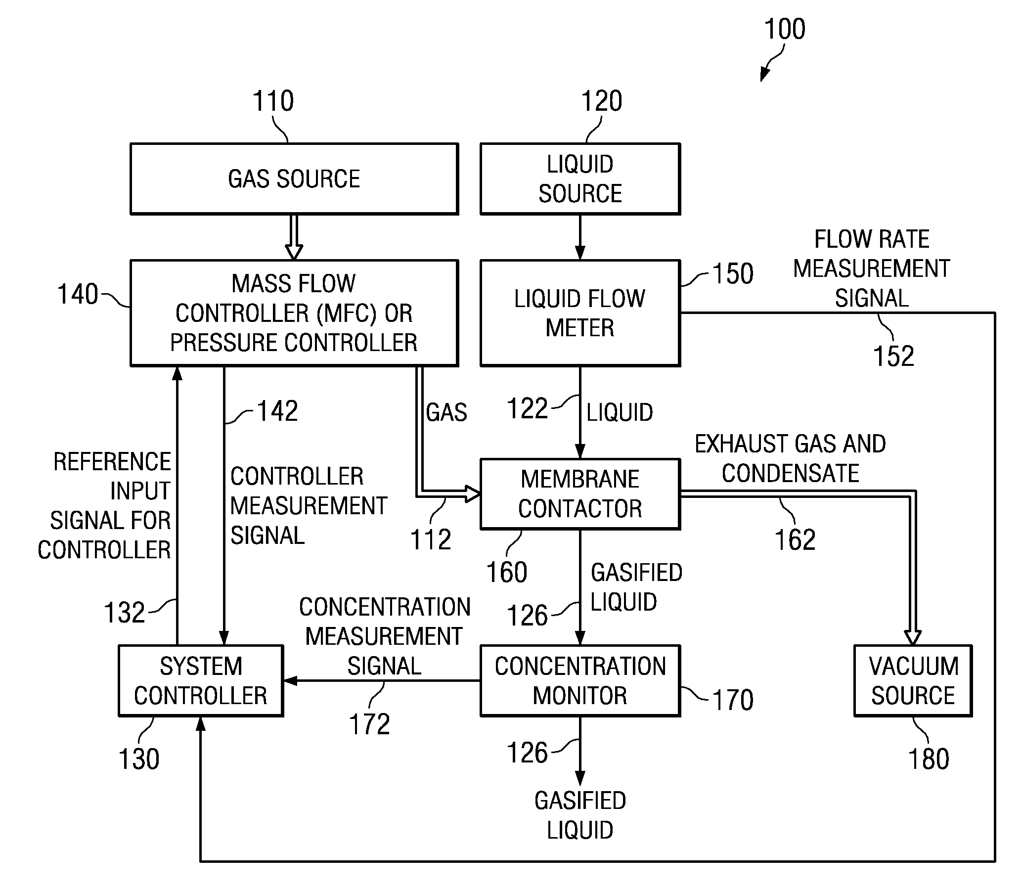
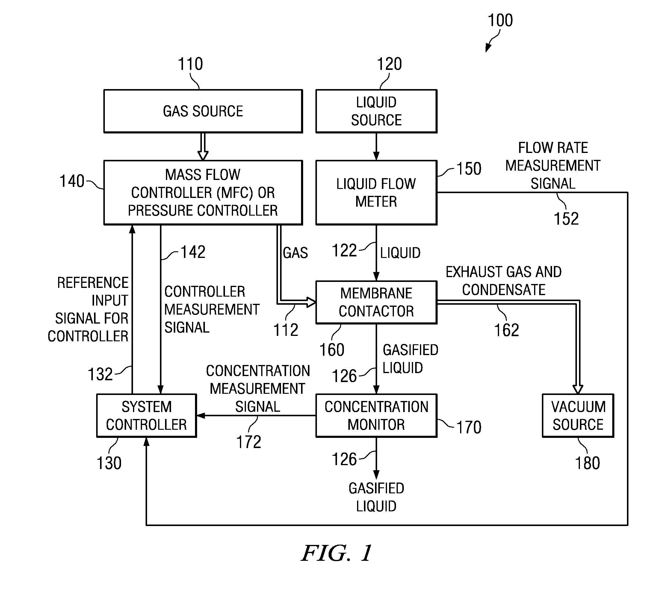
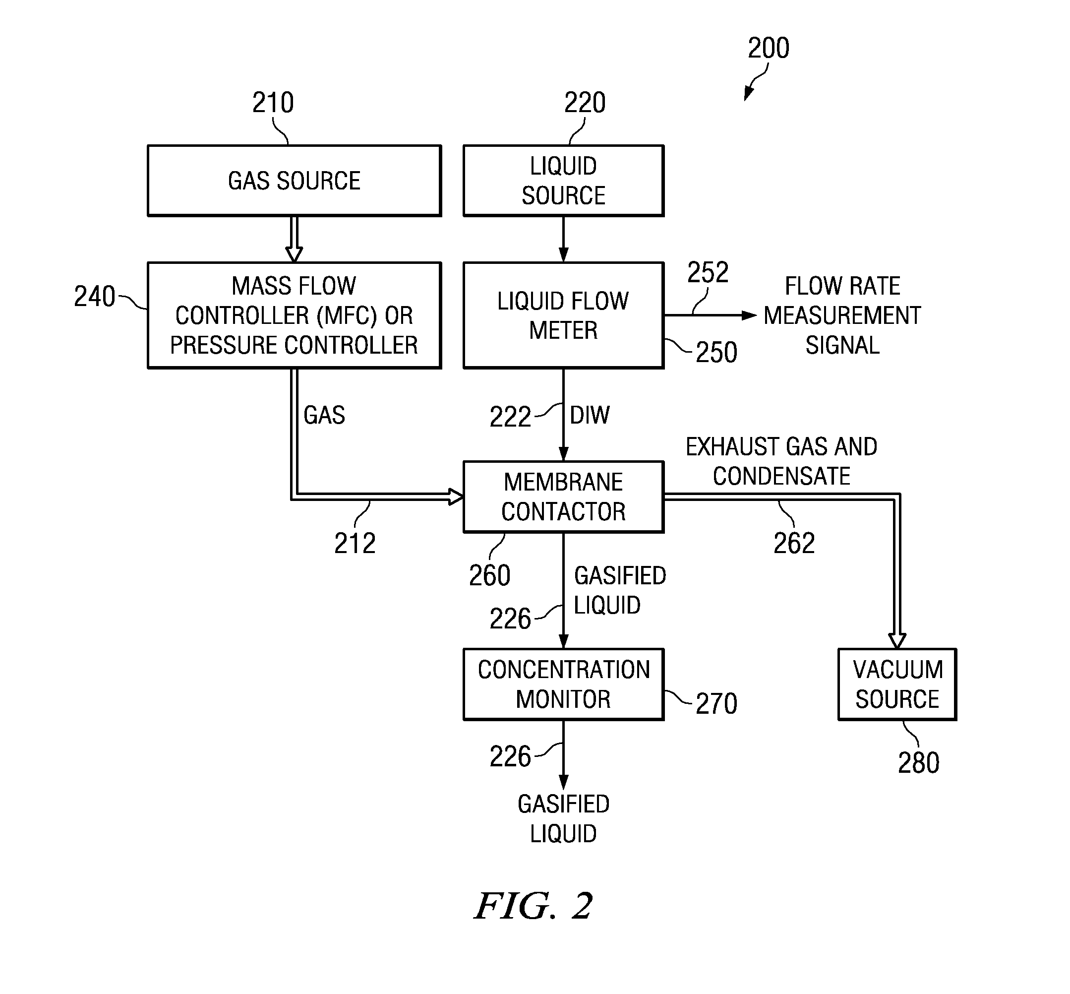
[0023]Embodiments of gasification systems and methods disclosed herein do not require any type of gas or fluid mixing, can eliminate the need for a diluting gas, can lower total gas consumption, and can be useful for a variety of semiconductor cleaning processes. These, and other, aspects will be better appreciated and understood when considered in conjunction with the following description and the accompanying drawings. The following description, while indicating various embodiments and numerous specific details thereof, is given by way of illustration and not of limitation. Many substitutions, modifications, additions or rearrangements may be made within the scope of the disclosure, and the disclosure includes all such substitutions, modifications, additions or rearrangements.

Problems solved by technology

The long time required to reach a steady state gas concentration in the liquid as measured from the start of gas flow into the contactor is not satisfactory for modern manufacturing processes and, in particular, not satisfactory for semiconductor processing.
Further, low gas flow rates are difficult to control, which makes the transfer of a gas into a liquid difficult to control.
The use of a reduced pressure unexpectedly results in a faster or shortened time to reach a steady state concentration of the gas in the liquid when compared to the use of the contactor without the reduced pressure.

Method used


Image

  • Gasification systems and methods for making bubble free solutions of gas in liquid
  • Gasification systems and methods for making bubble free solutions of gas in liquid
  • Gasification systems and methods for making bubble free solutions of gas in liquid

Examples


example 1

[0091]This example compares the times required to reach a steady state concentration of carbon dioxide dissolved in DI water with and without a source of reduced pressure connected to the gas outlet of a contactor. Referring to FIGS. 5A and 5B, the pressure at the gas outlet of the contactor was about −28 inches Hg (about 6 kPa). The time to reach a steady state when gas flow increase from 0 sccm to 1 sccm into 2 LPM flow of DI water at 22° C. was about 6.75 minutes without the reduced pressure (FIG. 5A) and less than two minutes with reduced pressure (FIG. 5B). The results show that providing reduced pressure at the gas outlet of the contactor gives a faster time (shorter) to reach a steady state concentration of dissolved gas in a liquid than without the reduced pressure. This example also shows that, by reducing the pressure on the gas contacting side of a contactor, the variation in the amount of gas in the liquid composition can be reduced. For example, the estimated variation ...

example 2

[0092]Table 2 below shows the large amounts of CO2 gas and N2 diluent gas that need to be mixed in order to make a gasified water with a conductivity of about 1 μS / cm at a water temperature of 24.5° C. using a single pHasor® II contactor without vacuum.

TABLE 2WaterWaterPressureWater PressureFlowCO2N2(PSI)(PSI)DownstreamRateFlowFlowUpstreamDownstreamResistivity(LPM)(SCCM)(LPM)of pHasorof pHasor(μS / cm)1163338380.991.5173338380.982183332320.993203332321.004223332321.00

example 3

[0093]In some embodiments, low resistivity water can be produced with low flow rates of carbon dioxide gas and reduced pressure at the gas outlet of the contactor. Table 3 below shows that one embodiment of system 400 can maintain stability of 5% or less variation in the conductivity of a gasified liquid with reduced pressure and using a rotameter to control CO2 flow. More specifically, using CO2 / vacuum at −28 inches mmHg (6 kPa), one embodiment of system 400 can achieve a stable conductivity of 1 μS / cm with 5% variation or less, actually 3% variation or less, for the water flow range of 2 to 12 liter per minute (LPM).

TABLE 3WaterWaterWaterCO2VacuumFlow RateTempPressurePressureConductivityLevel(LPM)(° C.)(kPa)(PSI)(μS / cm)CO2 Flow(mmHg)224.544011.05 + / − 0.03Rotameter−28slightly open1023.512010.995 + / − 0.02 Rotameter−28slightly open1223.21401  1 + / − 0.02Rotameter−28slightly open


PUM

PropertyMeasurementUnit
pressureaaaaaaaaaa
conductivityaaaaaaaaaa

Abstract

Embodiments disclosed herein can introduce low amounts of gas in a liquid with fast response time and low variation in concentration. In one embodiment, a gas is directed into an inlet on a gas contacting side of a porous element of a contactor and a liquid is directed into an inlet on a liquid contacting side of the porous element of the contactor. The liquid contacting side and the gas contacting side are separated by the porous element and a housing. The gas is removed from an outlet on the gas contacting side of the porous element at a reduced pressure compared to the pressure of the gas flowing into the inlet of the contactor. A liquid containing a portion of the gas transferred into the liquid is removed from an outlet on the liquid contacting side of the porous element, producing a dilute bubble free solution.

Description

CROSS-REFERENCE TO RELATED APPLICATIONS[0001]This application claims priority from U.S. Provisional Patent Application No. 61 / 054,223, filed May 19, 2008, entitled “APPARATUS AND METHOD FOR MAKING DILUTE BUBBLE FREE SOLUTIONS OF GAS IN A LIQUID,” U.S. Provisional Patent Application No. 61 / 082,535, filed Jul. 22, 2008, entitled “APPARATUS AND METHOD FOR MAKING DILUTE BUBBLE FREE SOLUTIONS OF GAS IN A LIQUID,” U.S. Provisional Patent Application No. 61 / 095,230, filed Sep. 8, 2008, entitled “APPARATUS AND METHOD FOR MAKING DILUTE BUBBLE FREE SOLUTIONS OF GAS IN A LIQUID,” and U.S. Provisional Patent Application No. 61 / 101,501, filed Sep. 30, 2008, entitled “SYSTEM AND METHOD FOR MAKING DILUTE BUBBLE FREE SOLUTIONS OF GAS IN A LIQUID,” the entire contents of which are expressly incorporated herein by reference for all purposes.TECHNICAL FIELD[0002]The present invention relates generally to integrated circuit manufacturing and more particularly to embodiments of gasification systems and ...

Claims


Application Information

Patent Timeline
Patent Type & Authority Applications(United States)
IPC IPC(8): F15D1/00B01F3/04
CPCB01F3/04106B01F15/00207B01F3/04985B01F3/04439B01F2003/04404Y10T137/0318B01F23/231B01F23/231244B01F35/213B01F23/2319B01F23/29
Inventor XIA, YANAN ANNIENIERMEYER, J. KARLMOLLICA, ROSARIOCONNER, GREGG T.
Owner ENTEGRIS INC
Why Eureka
Try Eureka