Light-emitting arrangement

a technology of light-emitting arrangement and shielding structure, which is applied in the direction of semiconductor devices for light sources, lighting and heating apparatus, printed circuit aspects, etc., can solve the problems of mechanical robustness and uncomplicated arrangement, and achieve the effect of reducing the need for a separate shielding structure, saving space, and simplifying the manufacturing process

Inactive Publication Date: 2011-07-28
KONINKLIJKE PHILIPS ELECTRONICS NV
View PDF8 Cites 28 Cited by
  • Summary
  • Abstract
  • Description
  • Claims
  • Application Information

AI Technical Summary

Benefits of technology

Furthermore, the heat release member may be mounted at a position such that the control circuitry is electromagnetically shielded from the LED. By using the heat release member for electromagnetic shielding, the need for a separate shielding structure is reduced, thus saving space and also simplifying the manufacturing process, which will reduce cost.
Furthermore, in embodiments of the invention, the light-emitting arrangement comprises a plurality of LEDs, each LED being thermally connected to the at least one electrically and thermally conductive portion by at least one contact; and a heat release member for dissipating heat of the plurality of LEDs. Thus, a plurality of LEDs may be used with a single heat release member, hence simplifying the production of systems comprising multiple LEDs and also allowing many different designs of the light-emitting arrangement and / or a lighting system comprising the light-emitting arrangement.
Alternatively, the light-emitting arrangement may comprise a plurality of LEDs, each LED being thermally connected to the at least one electrically and thermally conductive portion by at least one contact, and a plurality of heat release members for dissipating heat generated by the plurality of LEDs, wherein heat of at least one of the plurality of LEDs is transferred along a heat transfer path extending from the at least one of the plurality of LEDs to at least one of the plurality of heat release members. By allowing high variation in the numbers of LEDs and heat release members, and in the ways of connection there between, the light-emitting arrangement according to embodiments of the invention enables many different designs.

Problems solved by technology

The arrangement is uncomplicated and also mechanically robust, since the heat release member is attached to the PCB and not to the LED package.

Method used


Image

  • Light-emitting arrangement
  • Light-emitting arrangement
  • Light-emitting arrangement

Examples


Embodiment Construction

The present invention will now be described more fully hereinafter with reference to the accompanying drawings, in which preferred embodiments of the invention are shown. This invention may, however, be embodied in many different forms and should not be construed as limited to the embodiments set forth herein; rather, these embodiments are provided for thoroughness and completeness, and fully convey the scope of the invention to the skilled addressee. Like reference characters refer to like elements throughout.

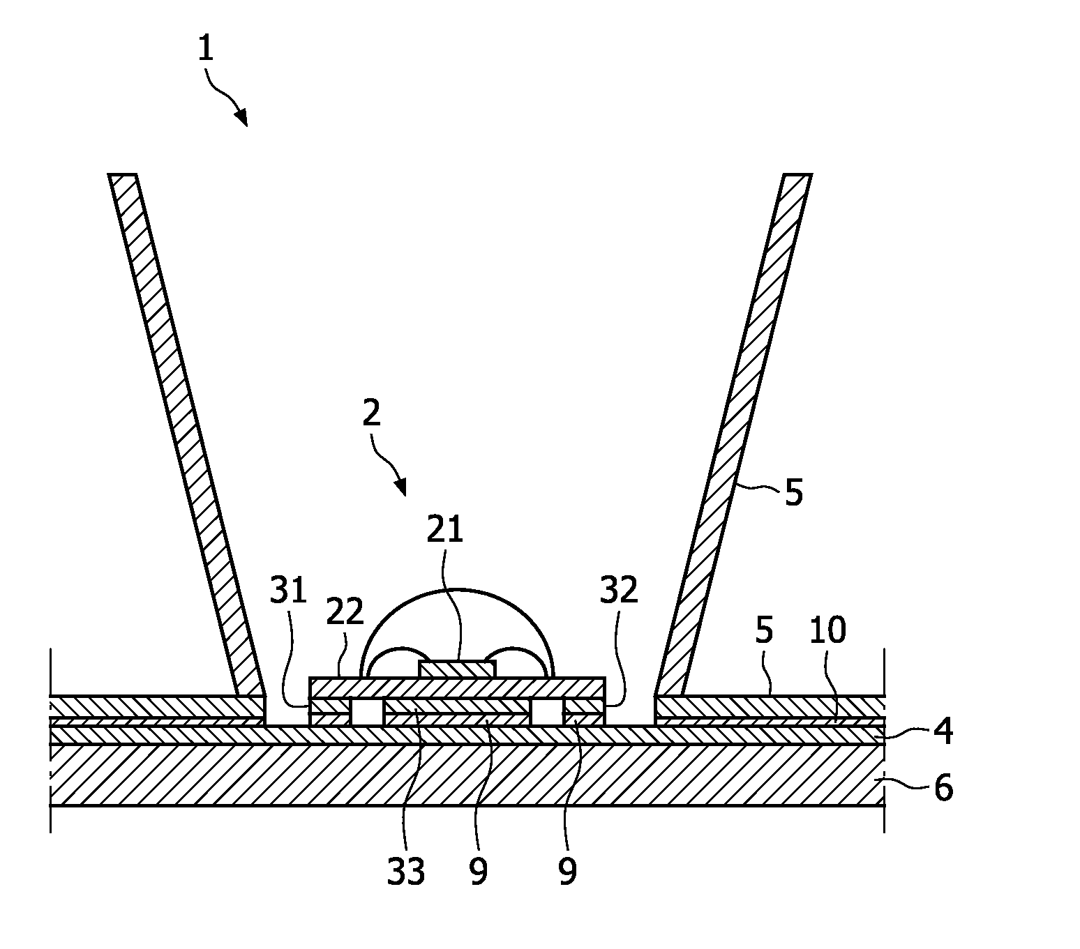
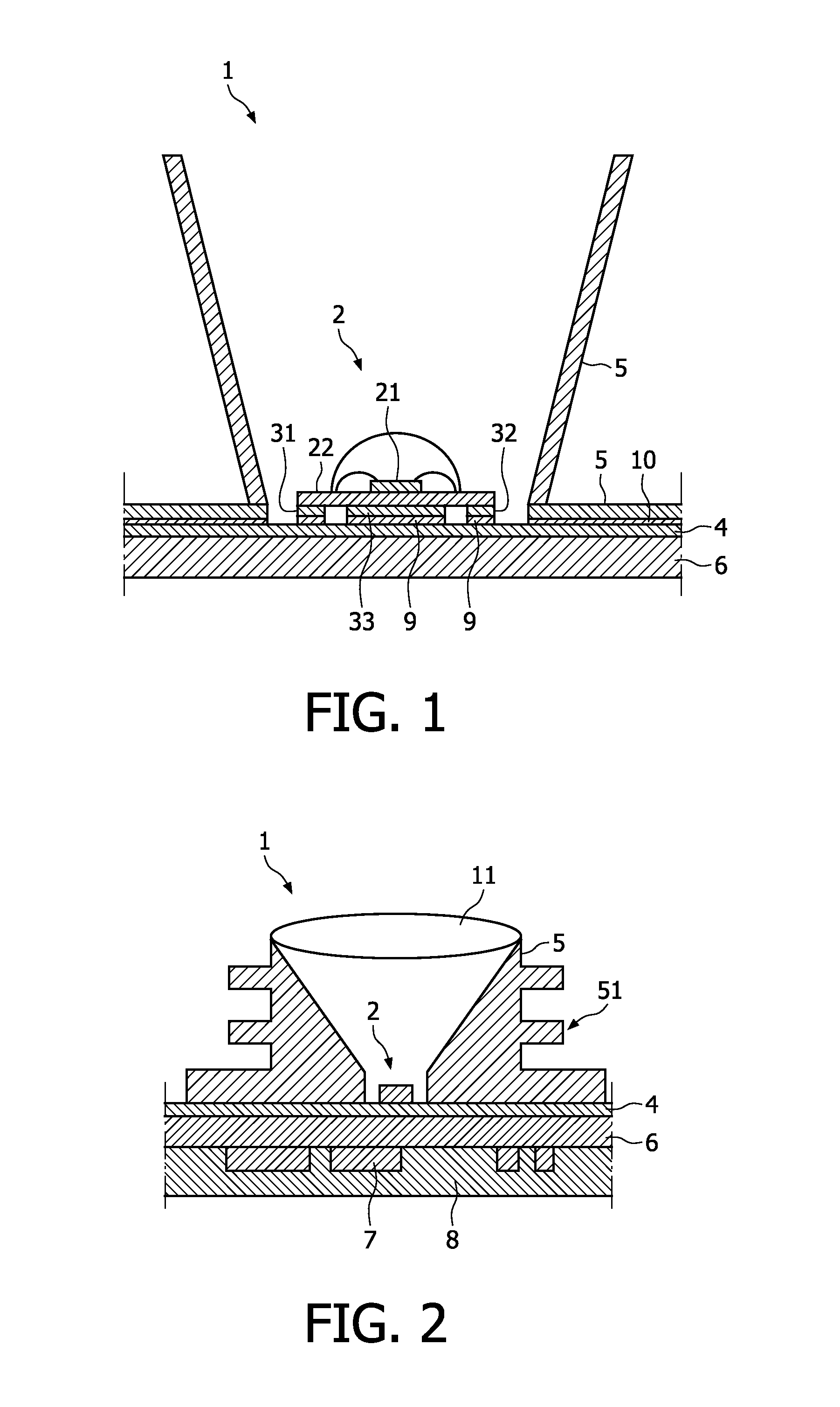
FIG. 1 shows a light-emitting arrangement according to an embodiment of the invention. The light-emitting arrangement 1 comprises a light-emitting diode (LED) 2 mounted on a printed circuit board (PCB) 6. The LED 2 comprises an LED chip 21 arranged on a substrate 22 and electrically and thermally connected to electric contacts 31, 32. The electric contacts 31, 32 are electrically and thermally connected to at least one electrically and thermally conductive portion 4 of the PCB...


PUM


Abstract

The invention relates to a light-emitting arrangement comprising a printed circuit board, PCB, having at least one electrically and thermally conductive portion, a light-emitting diode, LED, being thermally connected to the at least one electrically and thermally conductive portion by at least one contact of the LED, and a heat release member for dissipating heat generated by the LED, the heat release member being thermally connected to the at least one electrically and thermally conductive portion, wherein the heat generated by the LED is transferred along a heat transfer path extending from the LED via the at least one contact and the at least one electrically and thermally conductive portion to the heat release member.
The light-emitting arrangement according to the invention provides greatly improved heat removal from the LED while using a low-cost glass-epoxy material for the PCB.

Description

FIELD OF THE INVENTIONThe present invention relates to a light-emitting arrangement comprising a light-emitting diode (LED) and a heat release member for dissipating heat generated by the LED.BACKGROUND OF THE INVENTIONLight emitting diode (LED) based light-emitting devices are today increasingly used for a wide variety of lighting applications. One problem with LEDs is that they produce heat which must be removed from the device in order to avoid damage of the LED and the device. Overheating may also reduce the performance and / or the efficiency of the LED.Conventionally, a heatsink placed on the backside (opposite side to the LED) of a printed circuit board (PCB) onto which the LED has been arranged has been used for removing heat, thus requiring the heat to be transported through the PCB. In order to improve the heat transfer, metal core PCBs (MCPCBs) have been used, however having drawbacks as they are expensive. In contrast, glass-epoxy is a low-cost, easily processed material c...

Claims


Application Information

Patent Timeline
Patent Type & Authority Applications(United States)
IPC IPC(8): H01L33/64
CPCF21K9/00F21V29/767H01L33/60H01L33/62H01L33/642H01L33/647H05K1/0209H05K2201/066H05K2201/09781H05K2201/10106H01L2224/48091F21V29/004F21V29/505H01L2924/3025H01L2924/00012H01L2924/00H01L2924/00014F21K9/60F21Y2115/10
Inventor VAN ELMPT, ROB F. M.DE KONING, NIELSJACOBS, JEAN P.
Owner KONINKLIJKE PHILIPS ELECTRONICS NV
Why Eureka
Try Eureka