Method for analyzing the step-by-step injection rate provided by a fuel injection system used in a high power heat engine

a fuel injection system and step-by-step technology, which is applied in the direction of machines/engines, relative volume flow measurements, instruments, etc., can solve the problems of small wall thickness, increased piston diameter, and inability to meet the needs of the customer

Inactive Publication Date: 2011-08-04
EFS SA
View PDF6 Cites 4 Cited by
  • Summary
  • Abstract
  • Description
  • Claims
  • Application Information

AI Technical Summary

Benefits of technology

[0021]The present invention aims to avoid these difficulties, and it therefore aims to provide a solution of the type cons

Problems solved by technology

The production to that end of a larger measuring device, simply homothetic of the known device recalled above, faces difficulties in making the second measuring chamber, i.e. the variable-volume chamber used to perform a volume measurement via the movement of a piston.
However, regarding the second, variable-volume measuring chamber with interior piston, difficulties arise, because this chamber must meet very strict technical imperatives, the main imperatives being:The piston must slide perfectly, without locking or leaks, in the cylinder that delimits the measuring chamber, while the overall temperature of this chamber is generally kept relatively low, typically between 40 and 70° C., but the instantaneous temperature at the nose of the injector is high and can exceed 200° C. for modern injection sys

Method used


Image

  • Method for analyzing the step-by-step injection rate provided by a fuel injection system used in a high power heat engine
  • Method for analyzing the step-by-step injection rate provided by a fuel injection system used in a high power heat engine
  • Method for analyzing the step-by-step injection rate provided by a fuel injection system used in a high power heat engine

Examples


Embodiment Construction

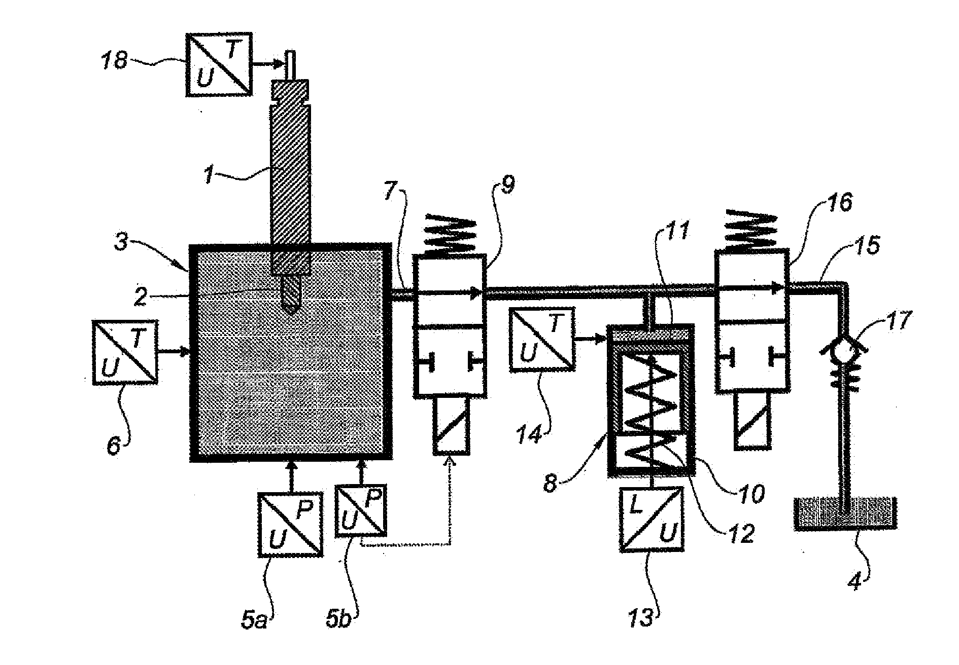
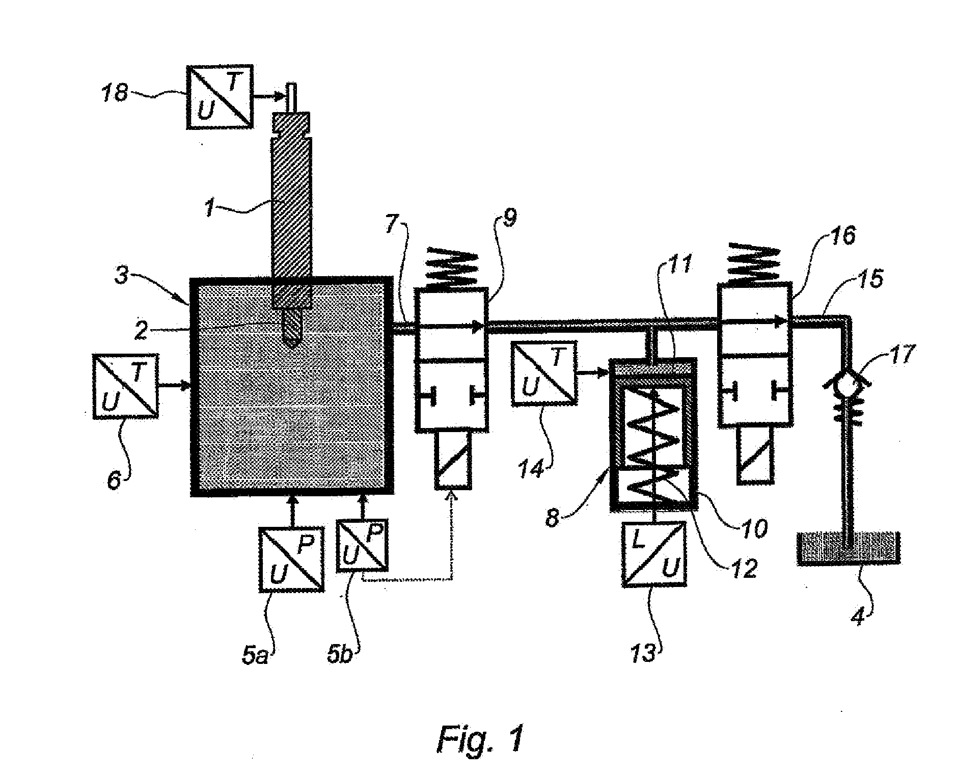
[0039]FIG. 1 shows an injector 1, the injection nozzle 2 of which is in a first measuring chamber 3, which is a constant-volume chamber. The first measuring chamber 3 is, in use, filled with a fluid that has hydraulic characteristics close to those of a fuel, but has a much higher flash point temperature than that of a fuel, in order to minimize the risks of fire and explosion. This fluid is also the fluid used in the injector 1. A reservoir 4 of this fluid is provided in the device.

[0040]In the illustrated example, the first measuring chamber 3 advantageously includes, as pressure sensor, a dynamic pressure converter 5a and a static pressure converter 5b. The dynamic pressure converter 5a, which can be made in the form of a piezoelectric converter, is responsible for measuring the dynamic component for which one seeks a high resolution—typically 0.001 bar—and a quick response. The static pressure converter 5b, which can be made in the form of a piezoresistive converter, is responsi...


PUM


Abstract

The method of the invention includes the injection of fuel in a first constant-volume measuring chamber (3) in which the pressure (P) and the temperature (T) are measured, and the partial draining of said first chamber into a second variable-volume measuring chamber (8) based on the movement of a piston (11), said movement being measured, wherein the partial draining of the first chamber into the second chamber after an injection is carried out until the pressure (Po) existing in the first chamber before the injection is recovered. The draining of the first chamber into the second after each injection is carried out several times consecutively, and the second chamber itself is drained each time. The volumetric measures made by moving the piston (11) for each filling/draining of the second chamber are added in order to obtain a total volume. The method is useful for high injection rates.

Description

TECHNICAL FIELD[0001]The present invention relates to a method making it possible to analyze the step-by-step injection rate provided by a fuel injection system used in a heat engine. The concerned injection systems are in particular those equipping diesel engines. The invention described here is more particularly applicable to injection systems used in high power engines, therefore injection systems with a high fuel flow.BACKGROUND[0002]Measuring devices are already known for allowing the builders of injection systems and heat engines to develop injectors as well as perform adjustments and compliance verifications during production and during the installation of these systems for their final use. These measuring devices are used in conjunction with a specific test block, the role of which is primarily to drive the rotation of an injection pump and support the different elements of the injection system during tests. The measurements done with these types of devices must make it poss...

Claims


Application Information

Patent Timeline
IPC IPC(8): G01F9/00
CPCG01F3/16F02M65/001
Inventor SCHMIDT, FRANCOIS
Owner EFS SA
Why Eureka
Try Eureka