
In-situ graphite shape control for iron castings

a graphite and shape control technology, applied in the direction of machines/engines, mechanical equipment, cylinders, etc., can solve the problem of inability to produce localized graphite morphology control, and achieve the effect of excellent thermal conductivity of grey iron

Inactive Publication Date: 2011-08-04
CATERPILLAR INC
View PDF0 Cites 5 Cited by
  • Summary
  • Abstract
  • Description
  • Claims
  • Application Information

AI Technical Summary

Benefits of technology

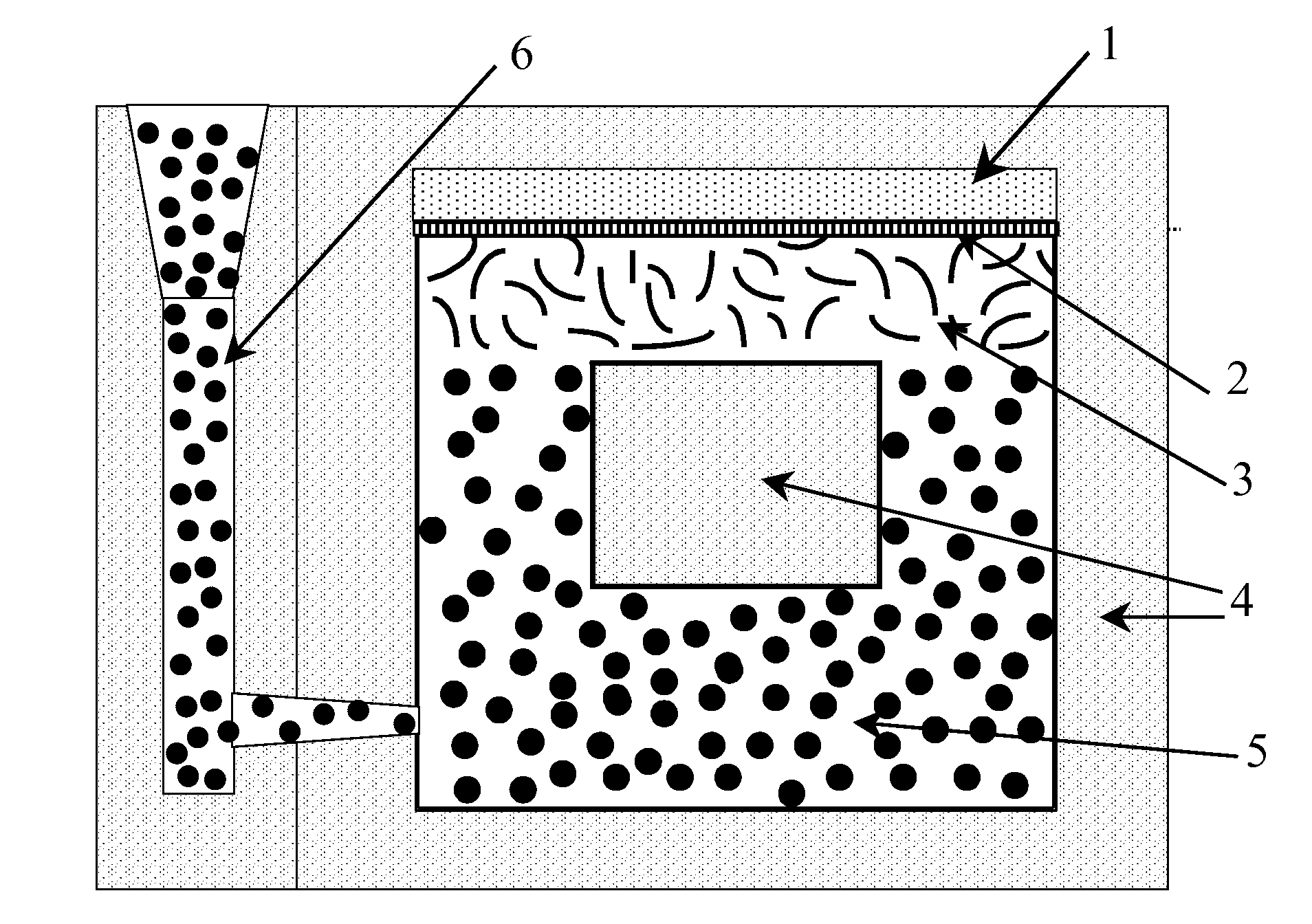
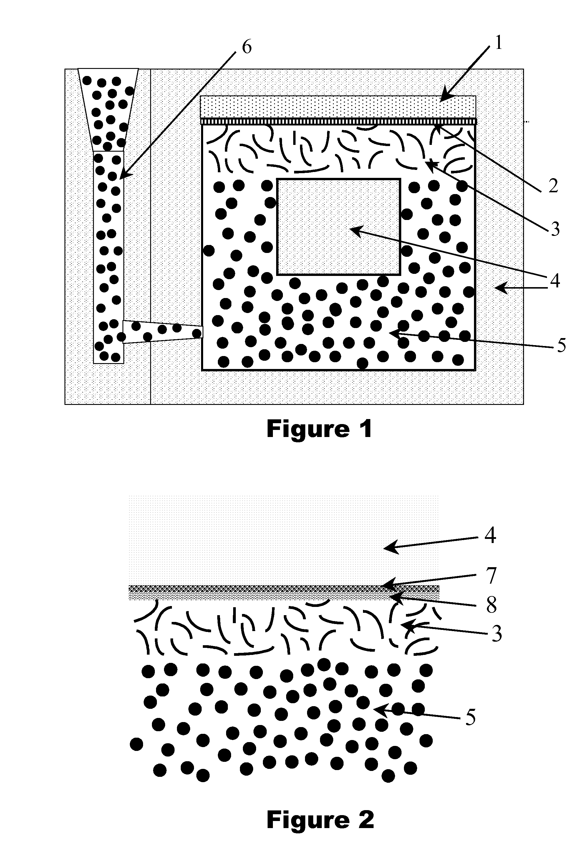
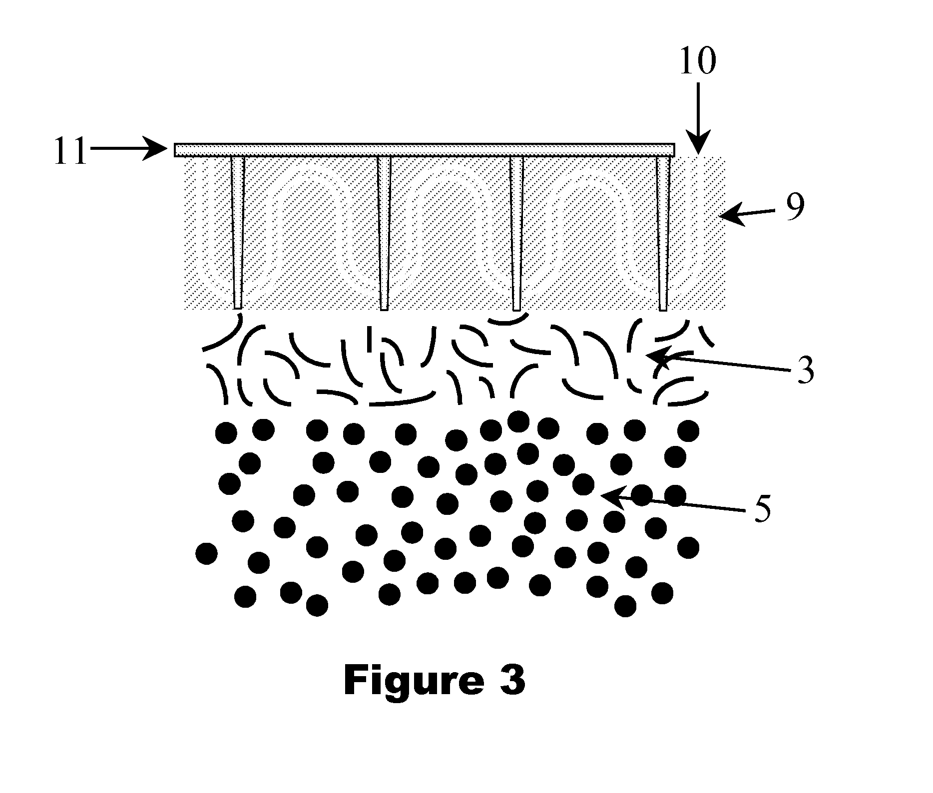
This disclosure relates to localized graphite morphology control using one or more of the following variables: in-situ treatment with sulfurizing agent, in-situ treatment with spheroidizing agent, pouring temperature control, and localized in-mold cooling rate control.
In another aspect of this disclosure, in-situ treatment with sulfurizing agent is designed with intentional latency. Whereas core wash treatments may become incorporated quickly and become evenly dispersed throughout the cast iron article, this disclosure proposes a system where sulfurizing agent is not incorporated into the cast iron article until some predetermined elapsed time after pouring. The latency period is defined as the time between pouring the molten iron into the mold and the time that the graphite morphology control agent is introduced into the molten iron.
In another aspect of this disclosure, graphite morphology control is used for cast iron engine parts such as cylinder heads, engine blocks, or cylinder liners. The reasons for using graphite morphology control may be different for the various components. For example, in a cylinder head it may be desirable to have flake graphite at the flame deck for the excellent thermal conductivity of grey iron while ductile iron may be desired at regions away from the flame deck for its mechanical fatigue strength. As another example, in an engine block it may be desirable to have flake graphite at the cylinder bore for grey iron's lubricity and ductile iron elsewhere for its tensile strength.

Problems solved by technology

Work conducted in conjunction with the present disclosure has shown that in-mold treatments of the type described in the prior art result in extensive mixing of the sulfurizing agent and thus are unable to produce localized graphite morphology control; despite what is disclosed in the prior art.

Method used


Image

  • In-situ graphite shape control for iron castings
  • In-situ graphite shape control for iron castings
  • In-situ graphite shape control for iron castings

Examples


Embodiment Construction

In one embodiment, a cast iron article is made with localized graphite morphology control using in-situ sulfurizing agent addition. The in-situ sulfurizing agent addition is achieved with intentional latency to prevent the sulfurizing agent from dispersing throughout the cast iron article. Casting simulations have shown that cast iron metal remains fluid and has sustained internal mixing for over 40 seconds after pouring for articles with dimensions of ˜360 mmט270 mmט150 mm. This internal mixing requires that any localized graphite morphology control must begin only after internal mixing subsides. Therefore, sulfurizing agent addition must have intentional latency commensurate with the duration of internal mixing after pouring.

It is common to construct a mold for a cast iron article to include one or more internal cores. Traditionally, each core section is made with substantially the same materials and each section exhibits similar thermal conductivity. In the present disclosure, ...


PUM

PropertyMeasurementUnit
depthaaaaaaaaaa
depthaaaaaaaaaa
thicknessaaaaaaaaaa

Abstract

A method to produce cast iron articles with various graphite morphologies is disclosed that provides cast iron with tailored properties at different locations of the article. Flake graphite morphology is preferably created at locations requiring excellent thermal conductivity or lubricity. Spheroidal graphite morphology is preferably created at locations requiring excellent strength or mechanical fatigue life. These methods may be particularly valuable for the production of heavy duty diesel engine components.

Description

TECHNICAL FIELDThis disclosure relates to graphite morphology control in cast iron articles.BACKGROUNDCast iron articles can be manufactured with graphite morphology selected from a number of different shapes based on the mechanical, thermal, chemical, and tribological properties desired. Cast iron with flake graphite, called grey iron, exhibits excellent castability, good thermal conductivity, and excellent lubricity due to the graphite flakes. Cast iron with nodular graphite (also called spheroidal graphite) is generically called ductile iron due to its improved ductility over cast iron containing flake graphite. Ductile iron has better wear resistance and better tensile strength than cast iron with flake graphite. A third common graphite morphology is vermicular graphite (also called compacted graphite) which bridges nodular graphite and flake graphite. It is characterized by interconnected networks of thickened and rounded flakes within an iron matrix. Vermicular graphite cast i...

Claims


Application Information

Patent Timeline
Patent Type & Authority Applications(United States)
IPC IPC(8): F02B75/22B22D27/00B22D27/04C22C37/04F02F1/24F02B75/18
CPCB22D27/00B22D27/04F02B75/22F02F1/24F02B75/18C22C37/04C22C37/10B22D19/0009C22C33/08C21D5/00C22C37/00
Inventor MCKIMPSON, MARVIN G.BARLOW, JAMES O.KOKOS, GEORGE B.
Owner CATERPILLAR INC
Learn More