Wheel Bearing Unit

a technology of bearing unit and wheel bearing, which is applied in the direction of bearing unit rigid support, machines/engines, liquid fuel engines, etc., can solve the problems of high production cost and previously known design of wheel bearing uni

Active Publication Date: 2011-08-04
AB SKF
View PDF7 Cites 19 Cited by
  • Summary
  • Abstract
  • Description
  • Claims
  • Application Information

AI Technical Summary

Benefits of technology

[0019]In some embodiments, the first and / or second part of the hub element is provided with a coating to protect the parts against corrosion during service conditions. The coating may consists of a sacrificial metal, e.g. a zinc coating, to provide the parts of the hub element with cathodic protection. A passive, corrosion-preventing coating is also possible.

Problems solved by technology

This previously known design of a wheel bearing unit is quite complex and is expensive to produce.

Method used


Image

  • Wheel Bearing Unit
  • Wheel Bearing Unit
  • Wheel Bearing Unit

Examples


Embodiment Construction

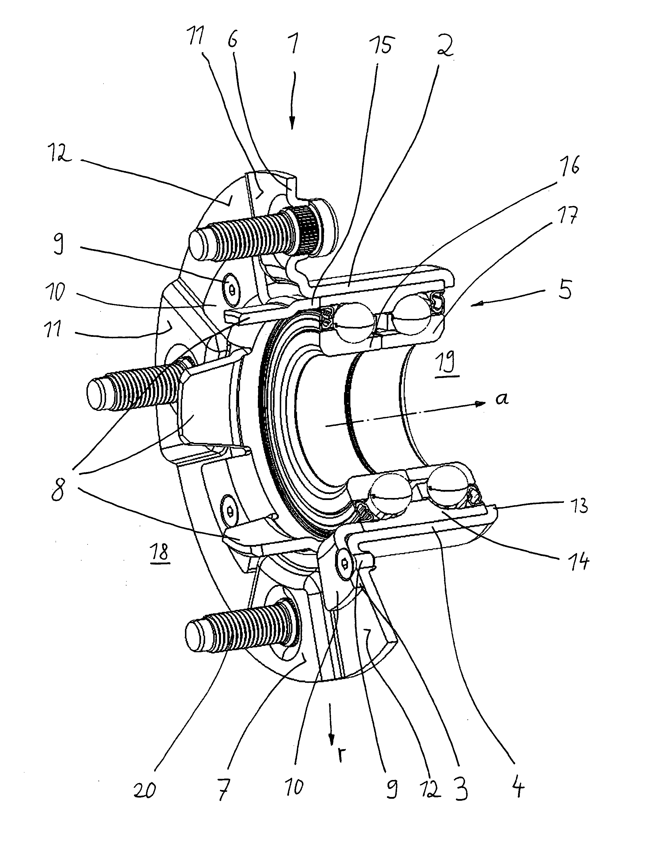
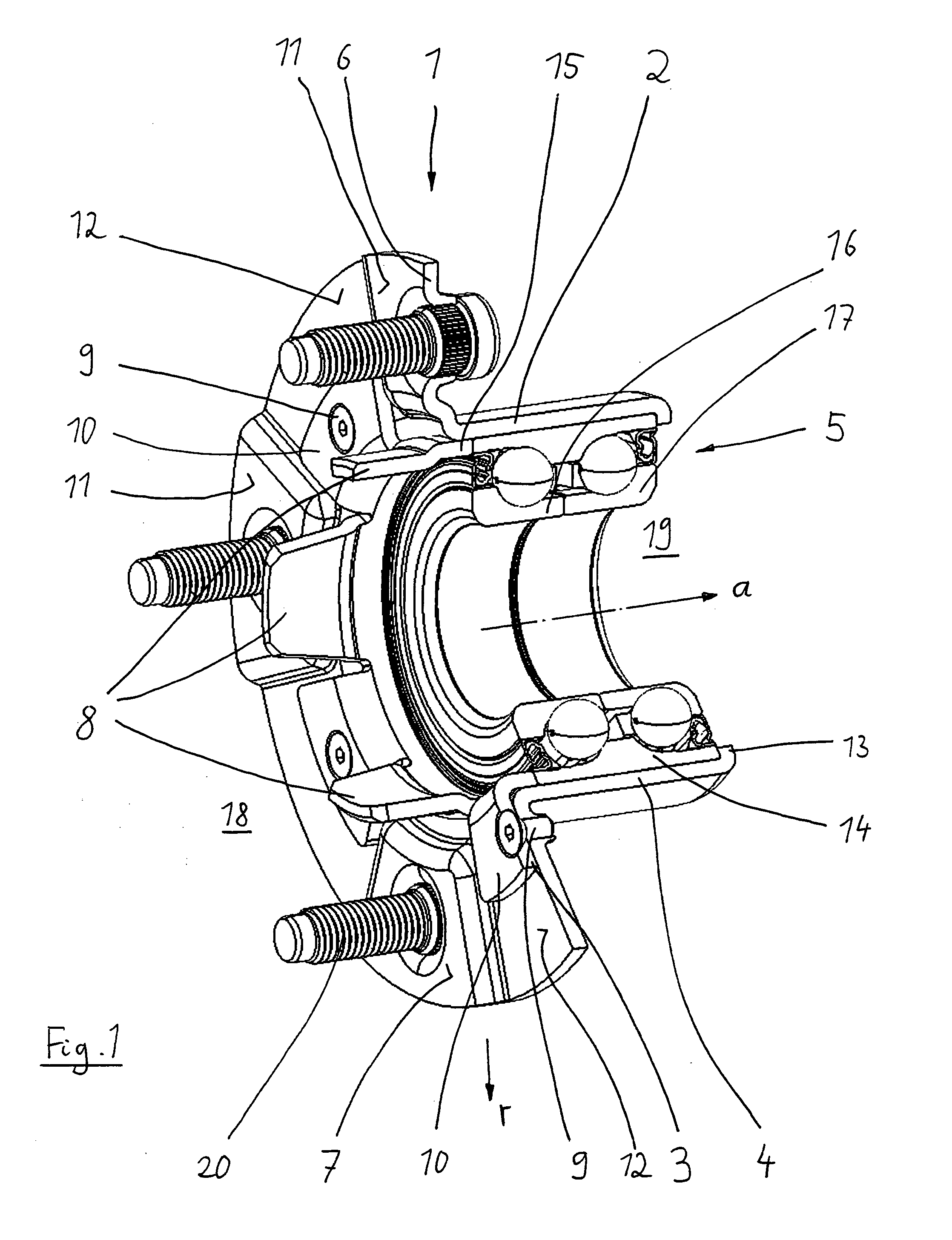
[0024]FIG. 1 shows a wheel bearing unit 1 which is used to support a vehicle wheel (not shown) relatively to an axle (also not shown). The vehicle wheel would be in the space marked with the reference numeral 18. The axle would be in the space marked with the reference numeral 19.

[0025]The wheel bearing unit 1 consists substantially of a hub element 2, 3 and a bearing arrangement 5 which supports the hub element 2, 3, i.e. the hub element 2, 3, can rotate but it is supported without any possibility of movement in axial (a) and radial (r) direction. In the depicted embodiment the bearing arrangement 5 is a double-row annular contact ball bearing with a single outer ring 14 with two raceways and two inner rings 16 and 17, where the raceways are equal in diameter. Here, a non-driven application is shown where the outer ring of the bearing arrangement is rotating and the inner rings are stationary.

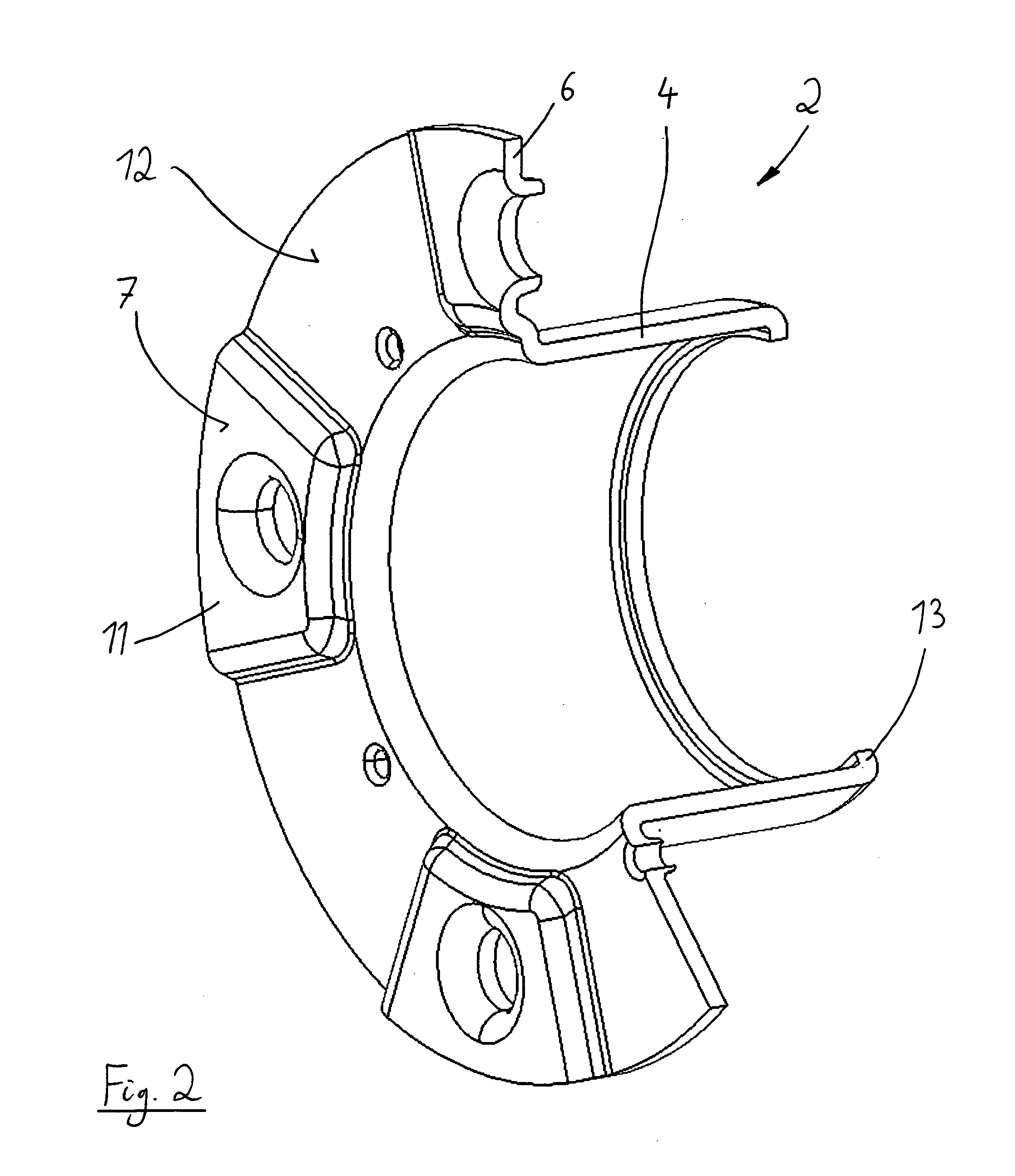
[0026]The hub element 2, 3 consists of two parts, namely a first part 2 and a second part ...


PUM


Abstract

The invention relates to a wheel bearing unit (1) for a vehicle wheel, comprising a hub element (2, 3) which has a axially (a) extending cylindrical section (4) to be supported by a bearing arrangement (5) and which has a radially (r) extending flange section (6) for fixing the vehicle wheel and/or a brake disk at a face side (7) of the flange section (6). To ensure a simple design with high stability the invention is characterized in that the hub element (2, 3) consists of a first part (2) comprising the cylindrical section (4) and the flange section (6) and of a second part (3), wherein the second part (3) has means (8) for centering a wheel rim of the vehicle wheel and/or the brake disk and wherein the first part (2) and the second part (3) are connected by connection means (9).

Description

TECHNICAL FIELD[0001]The invention relates to a wheel bearing unit for a vehicle wheel, comprising a hub element which has an axially extending cylindrical section to be supported by a bearing arrangement and which has a radially extending flange section for fixing the vehicle wheel and / or a brake disk at a face side of the flange section.BACKGROUND[0002]A wheel bearing unit of this kind is shown for example in WO 2008 / 000283 A1. Here a cylindrical sleeve element forms a part of the wheel bearing unit and is supported by a two-row angular contact ball bearing. Radially extending flange elements are formed at the cylindrical sleeve element to support a brake disk which can thus be fixed at the hub element. A vehicle wheel is then mounted by attaching it at one of the face sides of the brake disk.[0003]This previously known design of a wheel bearing unit is quite complex and is expensive to produce.SUMMARY OF THE INVENTION[0004]According to the invention, a design for a wheel bearing ...

Claims


Application Information

Patent Timeline
Patent Type & Authority Applications(United States)
IPC IPC(8): B60B27/00
CPCB60B27/0005F04C18/0269F16C19/184F04C23/008F16C35/067F04C23/001F16C35/045F16C2326/02F01C1/02F04C2/02F04C18/02
Inventor ZWARTS, JACOBUSVISSERS, COMELIUS PETRUS AANTONIUSVERHULST, LAURENSKAPAAN, JAN HENDRIKUS
Owner AB SKF
Why Eureka
Try Eureka