Secondary battery system

a secondary battery and battery technology, applied in the field of secondary battery systems, can solve the problems of affecting the service the deterioration of the life of secondary batteries, and the deterioration of the life of secondary batteries, and achieve the effect of increasing the capacity of secondary batteries

Inactive Publication Date: 2011-08-04
HITACHI LTD
View PDF3 Cites 20 Cited by
  • Summary
  • Abstract
  • Description
  • Claims
  • Application Information

AI Technical Summary

Benefits of technology

[0033]According to the present invention, without adding any special hardware, it becomes possible to simply and accurately detect the temporary increase in the direct current resistance of the secondary battery caused by charging and discharging a large current to and from the secondary battery capacity, on the basis of the relation between the direct current resistance of the secondary battery at the time of the charge and the direct current resistance of the secondary battery at the time of the discharge. Accordingly, even if such a temporary increase in the direct current resistance of the secondary battery, which largely affects the life of the secondary battery, occurs, the secondary battery can be properly managed.

Problems solved by technology

Further, it is known that, if an excessively large current is repeatedly charged to and discharged from the secondary battery capacity in a short period of time, the life of the secondary battery considerably deteriorates.
However, in the cases where a driving situation is rapidly changed, an abnormality in a charge and discharge management system occurs, and a secondary battery having a capacity which is excessively small compared with the used system is designed, a large current may be repeatedly charged to and discharged from the secondary battery capacity frequently and continuously for a long period of time.
In such a case, there is fear that the life of the secondary battery considerably deteriorates.
Further, if the charge and discharge is repeated again before the direct current resistance of the secondary battery which has temporarily increased sufficiently decreases, the life of the secondary battery considerably deteriorates.
However, according to the method disclosed in Japanese Patent Laid-Open Publication No. 2003-129927 (Patent Document 1), it is not possible to discriminate between the deterioration due to the transitional and temporary increase in direct current resistance as described above and the continuous deterioration over time, and hence the deterioration state of the secondary battery cannot be accurately detected.
As a result, there is fear that the temporary deterioration of the direct current resistance is erroneously determined as the continuous deterioration over time, and that the life of the secondary battery is rapidly shortened by performing the charge and discharge before the recovery from the transitional increase in direct current resistance.
Accordingly, the system is high in cost and complicated.

Method used


Image

  • Secondary battery system
  • Secondary battery system
  • Secondary battery system

Examples


embodiments

Embodiment 1

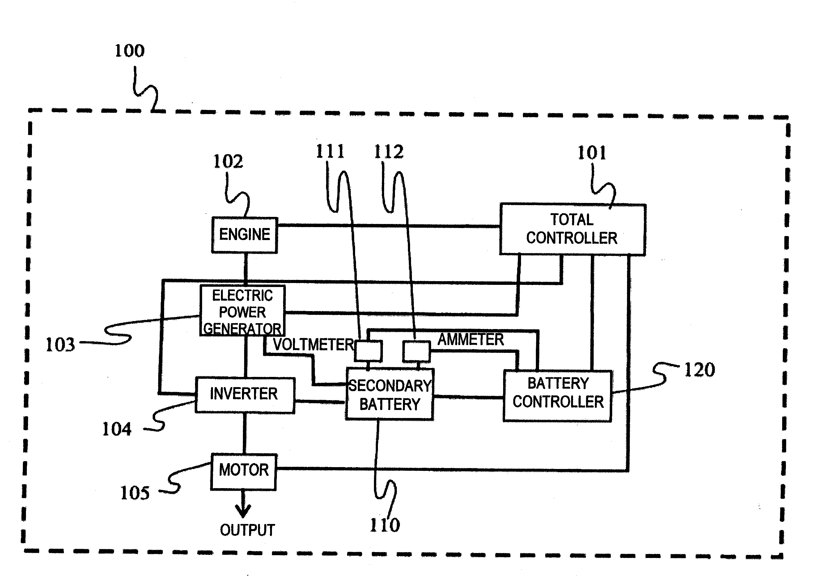
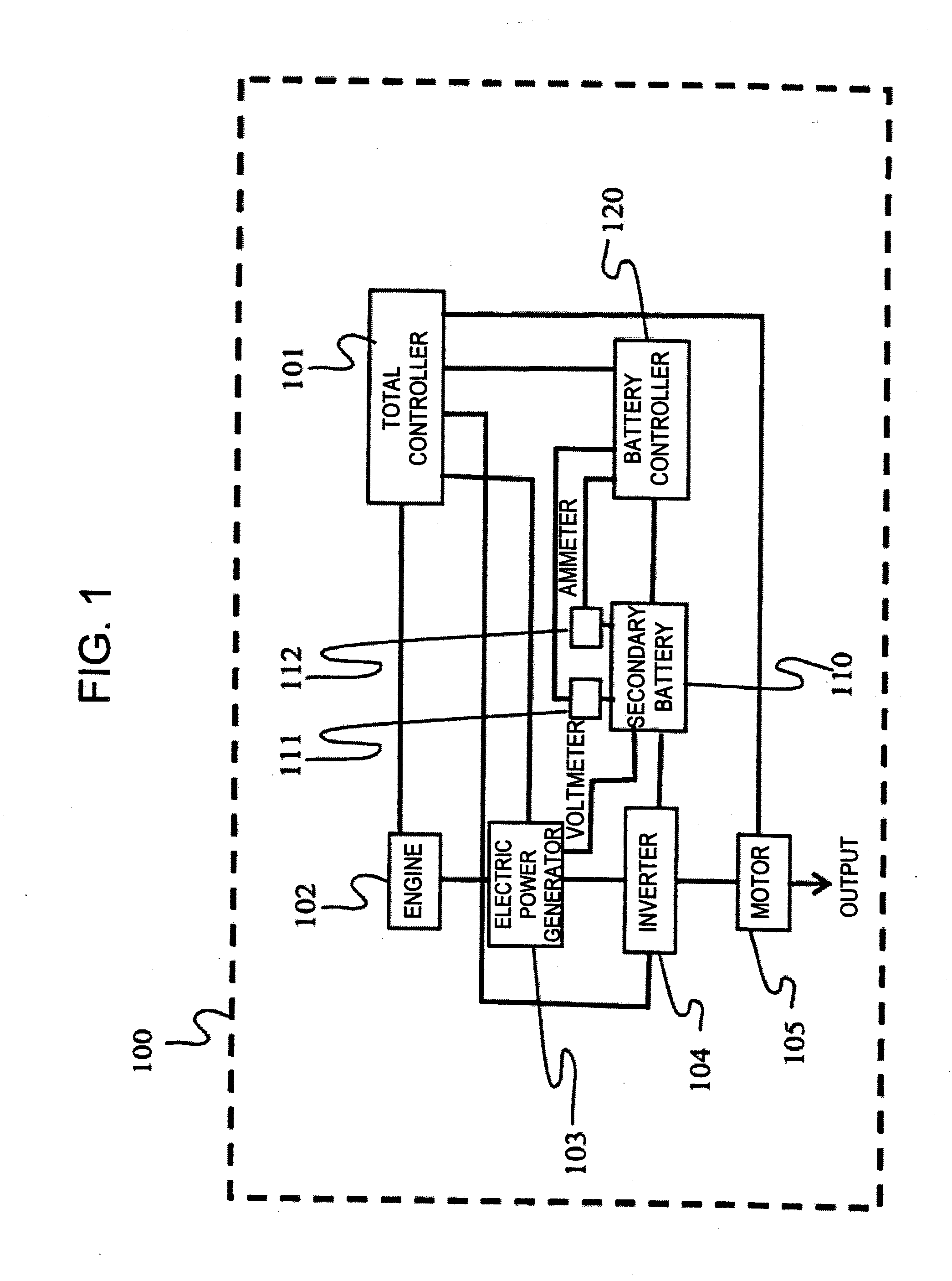
[0046]In the present embodiment, the present invention is applied to a hybrid system for automobiles, and a system configuration diagram is illustrated in FIG. 1. A hybrid system 100 includes an engine 102, an electric power generator 103, an inverter 104, a motor 105, a total controller 101, a secondary battery 110, a voltmeter 111, an ammeter 112, and a battery controller 120. An output of the engine 102 is converted into electric power by the electric power generator 103, and is connected to the motor 105 via the inverter 104. In addition, the secondary battery 110 is also connected to the motor 105 via the inverter 104.

[0047]The battery controller 120 calculates the state of the secondary battery and the upper limit value of electric power which can be charged and discharged, by means of the voltmeter 111, the ammeter 112, and the like connected to the secondary battery 110, and outputs the results to the total controller 101.

[0048]In the hybrid system 100, at the ti...

embodiment 2

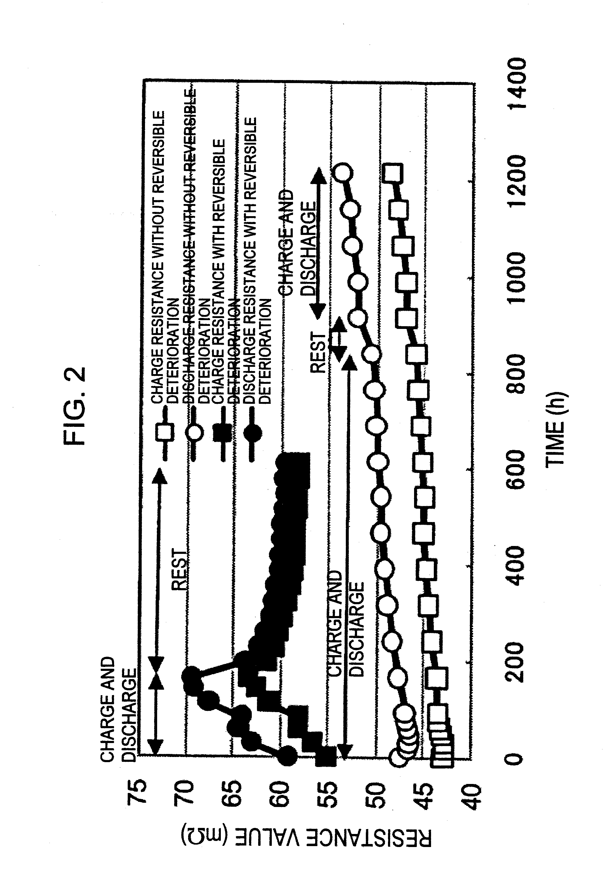
[0082]In order to judge the reversible resistance increase, in Embodiment 1, the change characteristic of the ratio of the discharge direct current resistance to the charge direct current resistance is utilized, and on the other hand, in the present embodiment, the rates of increase of the discharge direct current resistance and the charge direct current resistance are focused on.

[0083]That is, the values of the discharge direct current resistance and the charge direct current resistance in FIG. 2 are shown in FIG. 4 as the rates of increase when the values before the start of the experiment are assumed as 100%. Black plots represent results which are obtained when the charge and discharge experiment is performed on the capacity of the secondary battery at a high current density. Further, square plots represent a temporal change in the rate of increase of the charge direct current resistance, and circular plots represent a temporal change in the rate of increase of the discharge dir...

embodiment 3

[0091]In the present embodiment, description is given of an example in which the present invention is applied to a hybrid system for automobiles which operates a regeneration brake at the time of deceleration or downward slope driving.

[0092]FIG. 6 is a configuration diagram illustrating the hybrid system according to the present embodiment. A hybrid system 150 includes the engine 102, the electric power generator 103, the inverter 104, the motor 105, the total controller 101, the secondary battery 110, the voltmeter 111, the ammeter 112, the battery controller 120, and a converter 106. An output from the secondary battery 110 is connected to the motor 105 via the inverter 104. An output of the motor 105 is outputted as the power for driving a vehicle or the like, via the converter 106 together with an output of the engine 102.

[0093]Here, the converter 106 adjusts the ratio of the output of the engine 102 to the output of the motor 105, and performs such a control that the efficiency...


PUM

PropertyMeasurementUnit
charge currentaaaaaaaaaa
discharge currentaaaaaaaaaa
voltageaaaaaaaaaa

Abstract

Provided is a secondary battery system including: a battery controller which controls charge and discharge of a secondary battery; a total controller which controls the entire system; an ammeter which detects a charge current and a discharge current of the secondary battery; and a voltmeter which detects a voltage of the secondary battery, in which a direct current resistance of the secondary battery at the time of charge and a direct current resistance of the secondary battery at the time of discharge are obtained on the basis of a current value and a voltage value detected by the ammeter and the voltmeter, to thereby determine a temporary increase in the direct current resistance of the secondary battery caused by charge and discharge with a large current on the basis of a relation between the two obtained direct current resistances. Accordingly, in a secondary battery system used in a hybrid system, a wind power generating system, a photovoltaic power generating system, and the like, the situation where a direct current resistance thereof transitionally (temporarily) increases is simply detected on the basis of the usage situation of a secondary battery, to thereby accurately calculate the deterioration state of the secondary battery and thus enable an appropriate coping process, so that the life of the secondary battery can be extended.

Description

[0001]The present application is based on and claims priority of Japanese patent application No. 2010-017815 filed on Jan. 29, 2010, the entire contents of which are hereby incorporated by reference.BACKGROUND OF THE INVENTION[0002]1. Field of the Invention[0003]The present invention relates to a secondary battery system for a hybrid system, an electric power generating system, and the like on which a secondary battery is mounted.[0004]2. Description of the Related Art[0005]For automobiles, rail vehicles, and the like, there has been known a hybrid system in which a rechargeable battery such as a lead acid battery, a nickel metal hydride battery, and a lithium battery is mounted, electric power obtained by a regeneration brake is charged to the rechargeable battery, and the electric power is utilized at the time of acceleration or the like, to thereby enhance fuel efficiency.[0006]In addition, for an electric power generating system which utilizes natural energy, such as wind power ...

Claims


Application Information

Patent Timeline
Patent Type & Authority Applications(United States)
IPC IPC(8): H01M10/46H02J7/04
CPCH01M10/425H01M10/44H01M10/482H01M10/448H01M10/48H01M10/441Y02E60/10
Inventor YAMAMOTO, TSUNENORIOKUMURA, TAKEFUMISASAKI, HIRONORI
Owner HITACHI LTD
Why Eureka
Try Eureka