Synchronization of projected illumination with rolling shutter of image sensor

a technology of image sensor and projection light, applied in the field of electronic imaging, can solve problems such as artifacts

Inactive Publication Date: 2011-08-04
APPLE INC
View PDF85 Cites 162 Cited by
  • Summary
  • Abstract
  • Description
  • Claims
  • Application Information

AI Technical Summary

Benefits of technology

[0005]Embodiments of the present invention that are described hereinbelow provide apparatus and methods for...

Problems solved by technology

The use of a rolling shutter introduces a temporal shear in the...

Method used


Image

  • Synchronization of projected illumination with rolling shutter of image sensor
  • Synchronization of projected illumination with rolling shutter of image sensor
  • Synchronization of projected illumination with rolling shutter of image sensor

Examples


Embodiment Construction

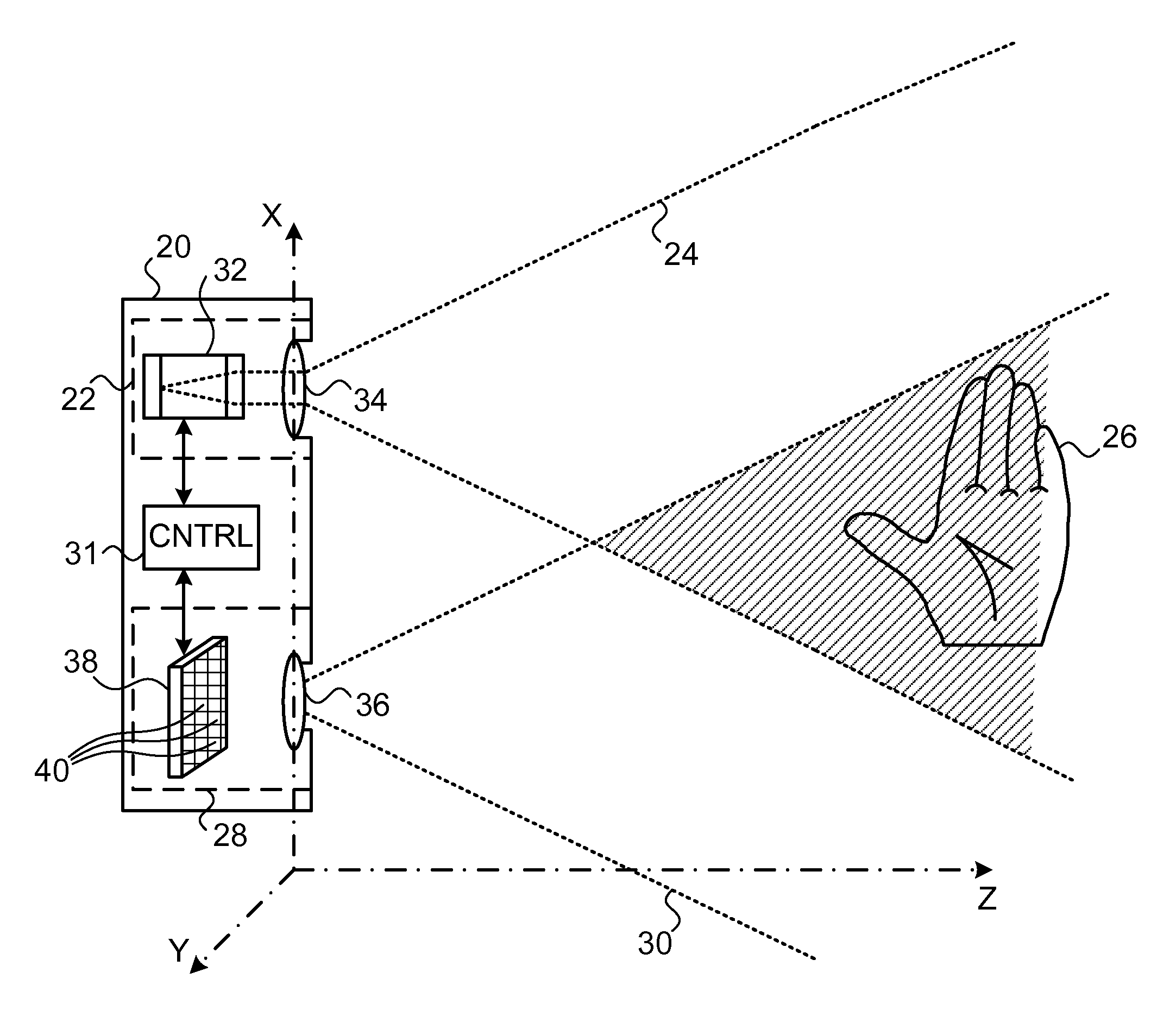
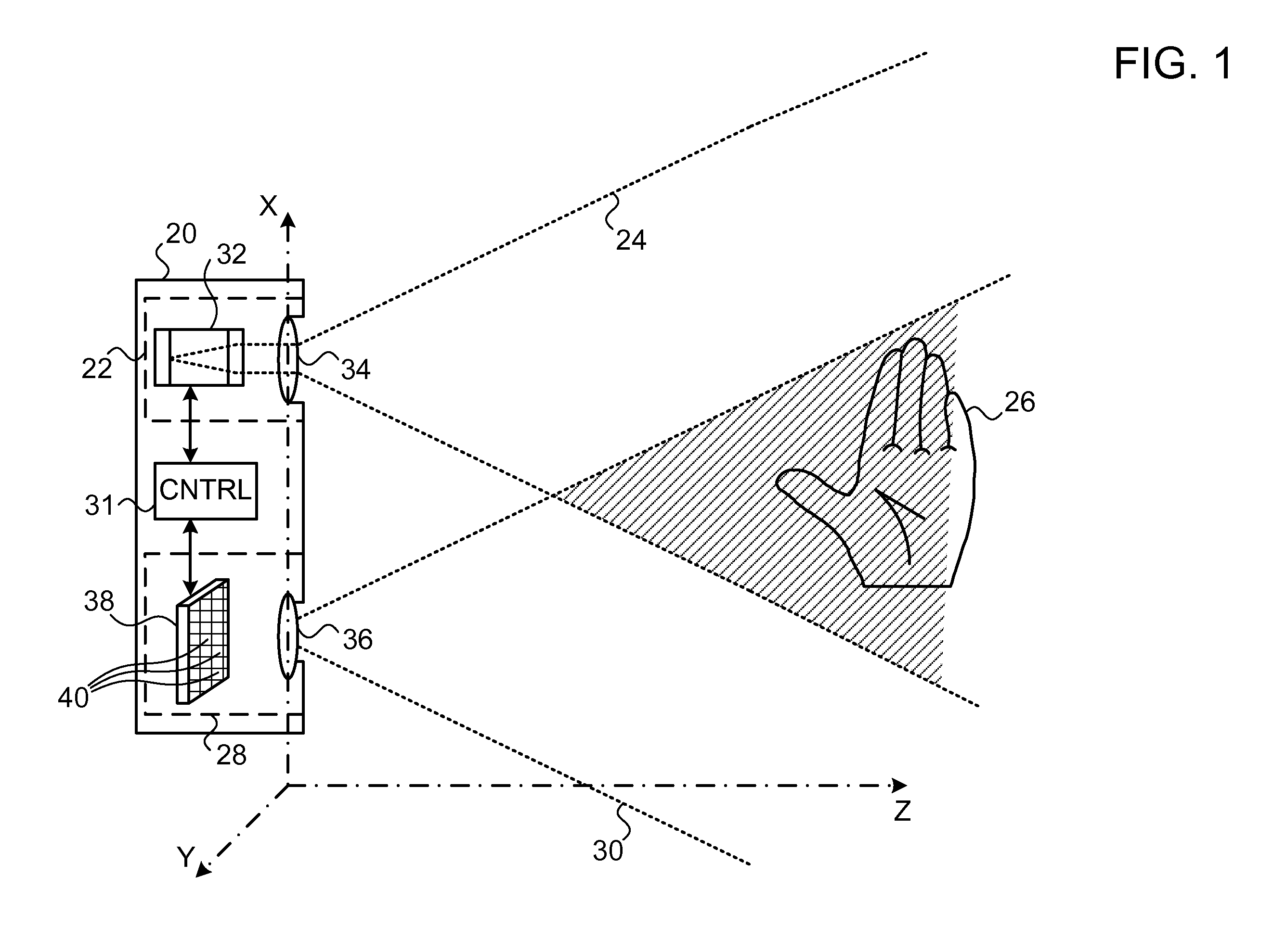
[0026]Various types of imaging systems include optical projectors for illuminating the scene of interest. For example, a projector may be used to cast a pattern of coded or structured light onto an object for purposes of three-dimensional (3D) depth mapping. In this regard, U.S. Patent Application Publication 2008 / 0240502, whose disclosure is incorporated herein by reference, describes an illumination assembly in which a light source, such as a laser diode or LED, transilluminates a transparency with optical radiation so as to project a pattern onto the object. (The terms “optical,”“light” and “illumination” as used herein refer generally to any of visible, infrared, and ultraviolet radiation.) An image sensor captures an image of the pattern that is projected onto the object, and a processor processes the image so as to reconstruct a three-dimensional (3D) map of the object.

[0027]Systems based on projection of patterned light may suffer from low signal / background ratio due to limit...


PUM


Abstract

Imaging apparatus includes an illumination assembly, including a plurality of radiation sources and projection optics, which are configured to project radiation from the radiation sources onto different, respective regions of a scene. An imaging assembly includes an image sensor and objective optics configured to form an optical image of the scene on the image sensor, which includes an array of sensor elements arranged in multiple groups, which are triggered by a rolling shutter to capture the radiation from the scene in successive, respective exposure periods from different, respective areas of the scene so as to form an electronic image of the scene. A controller is coupled to actuate the radiation sources sequentially in a pulsed mode so that the illumination assembly illuminates the different, respective areas of the scene in synchronization with the rolling shutter.

Description

CROSS-REFERENCE TO RELATED APPLICATION[0001]This application claims the benefit of U.S. Provisional Patent Application 61 / 300,465, filed Feb. 2, 2010, which is incorporated herein by reference.FIELD OF THE INVENTION[0002]The present invention relates generally to systems and methods for electronic imaging, and specifically to methods of illumination for enhancing the quality of captured images.BACKGROUND OF THE INVENTION[0003]Most low-cost CMOS image sensors use a rolling shutter, in which successive rows of sensor elements are triggered sequentially to capture light. This method of image acquisition thus records each individual frame not as a single snapshot at a point in time, but rather as a sequence of image stripes scanning across the frame. The result of the rolling shutter is that not all parts of the optical image are recorded at exactly the same time (although the frame is stored as a single electronic image).[0004]The use of a rolling shutter introduces a temporal shear in...

Claims


Application Information

Patent Timeline
IPC IPC(8): H04N5/225
CPCG02B27/0944G02B27/0972G02B27/0983H01L33/60H01S5/005H01S5/0071G02B19/0028H01S5/4031H01S5/423G03B15/06H04N13/0207G02B19/0057H01S5/02248G03B21/2033G03B21/2066G03B21/28H04N13/207H01S5/02325H01S5/02315H01S5/02255H01S5/02253H01S5/02257
Inventor MOR, ZAFRIRSHPUNT, ALEXANDER
Owner APPLE INC
Why Eureka
Try Eureka