Magnetoresistance element, mram, and initialization method for magnetoresistance element

a technology of magnetoresistance element and magnetic random access memory, which is applied in the direction of digital storage, semiconductor devices, instruments, etc., can solve the problems of increasing the number of processes, increasing the cost, and failure in which the domain wall does not stably mov

Active Publication Date: 2011-08-04
NEC CORP
View PDF2 Cites 21 Cited by
  • Summary
  • Abstract
  • Description
  • Claims
  • Application Information

AI Technical Summary

Benefits of technology

[0021]The present invention provides an element structure that requires only a small number of processing steps and avoids a domain wall motion failure, and a ...

Problems solved by technology

The formation of the structure in which the thicknesses of the first magnetization fixed portion 101 and the second magnetization fixed portion 102 are different from each other as in the case of WO2005/069368, however,...

Method used


Image

  • Magnetoresistance element, mram, and initialization method for magnetoresistance element
  • Magnetoresistance element, mram, and initialization method for magnetoresistance element
  • Magnetoresistance element, mram, and initialization method for magnetoresistance element

Examples


first embodiment

(Structure of Magnetoresistance Element)

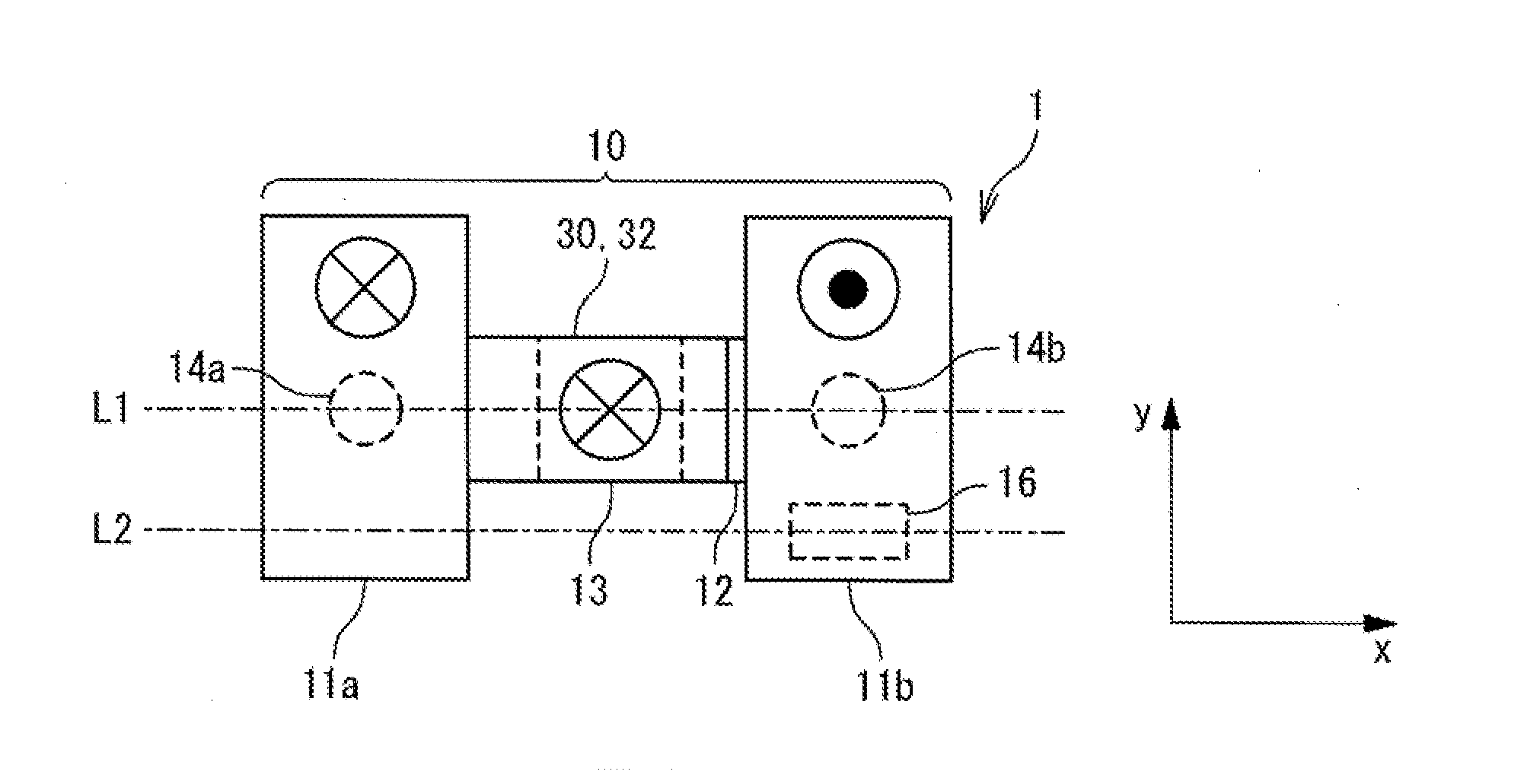
[0053]FIG. 3A is a plan view illustrating a structure of a magnetoresistance element 1 in a first embodiment, FIG. 3B is a cross-sectional view on the L1 cross section, and FIG. 3C is a cross-sectional view on the L2 cross section. As illustrated in FIG. 3A, the magnetoresistance element 1 is provided with a magnetization recording layer 10, a magnetization fixed layer 30, and a tunnel barrier layer 32 provided between them. The tunnel barrier layer 32 is a nonmagnetic dielectric layer, and formed of a thin dielectric film such as an Al2O3 film or a MgO film. The tunnel barrier layer 32 is sandwiched between the magnetization recording layer 10 and the magnetization fixed layer 30, and the magnetization recording layer 10, the tunnel barrier layer 32, and the magnetization fixed layer 30 form a magnetic tunnel junction (MTJ).

[0054]The magnetization recording layer 10 is a ferromagnetic layer having anisotropy in the direction perpendicular to ...

second embodiment

[0090]FIG. 9A is a plan view illustrating the structure of a magnetization recording layer 10 of a magnetoresistance element 1 in a second embodiment of the present invention, FIG. 9B is a cross-sectional view illustrating the structure on the L1 cross-section, and FIG. 9C is a cross-sectional view illustrating the structure on the L2 cross section. The magnetization recording layer 10 includes the first magnetization fixed region 11a, the second magnetization fixed region 11b, and the magnetization reversal region 13. As described above, the magnetization reversal region 13 refers to a region coupled to a tunnel barrier layer and a magnetization fixed layer (both not illustrated) constituting an MTJ.

[0091]In this embodiment, the via contact 14a, the second via contact 14b, and fourth via contacts 14c and 14d are coupled onto the lower surface of the magnetization recording layer 10. The via contacts 14a to 14d are formed in the same via formation process. The first magnetization fi...

third embodiment

[0102]FIG. 14A is a plan view illustrating a configuration of a magnetoresistance element 1 in a third embodiment of the present invention, and FIG. 14B is a cross-sectional view. In the third embodiment, a separating metal layer 38 and a sensing magnetic layer 39 are provided between a tunnel barrier layer 32 and the magnetization recording layer 10, and a film stack including the separating metal layer 38, the sensing magnetic layer 39, the tunnel barrier layer 32, and the magnetization fixed layer 30 is arranged at a position that is offset from the center of the magnetization recording layer 10 in the Y direction. Specifically, the sensing magnetic layer 39 is provided so that a portion thereof is opposed to the magnetization reversal region 13, and the tunnel barrier layer 32 is provided on the sensing magnetic layer 39. The magnetization fixed layer 30 is provided on the tunnel barrier layer 32 so as to be opposed to the sensing magnetic layer 39.

[0103]In the third embodiment,...


PUM


Abstract

A magnetoresistance element is provided with: a magnetization recording layer that is a ferromagnetic layer. The magnetization recording layer includes: a magnetization reversal region having a reversible magnetization; a first magnetization fixed region connected to a first boundary of the magnetization reversal region and having a magnetization direction fixed in a first direction; and a second magnetization fixed region connected to a second boundary of the magnetization reversal region and having a magnetization direction fixed in a second direction. At least one magnetization reversal facilitation structure which is a structure in which a magnetization is reversed more easily than the remaining portion is provided for a portion of the second magnetization fixed region.

Description

TECHNICAL FIELD[0001]The present invention relates to a magnetoresistance element and an MRAM (magnetic random access memory) using the same for a memory cell, and more particularly, to a technique for initialization of a domain wall motion type magnetoresistance element.BACKGROUND ART[0002]An MRAM is a promising nonvolatile memory from the perspective of high integration and high speed operation. In an MRAM, magnetoresistance elements exhibiting a “magnetoresistance effect” such as a TMR (tunnel magnetoresistance) effect are used. In a magnetoresistance element, a magnetic tunnel junction (MTJ) is formed, in which a tunnel barrier layer is sandwiched by two ferromagnetic layers, for example. One of the two ferromagnetic layers is a magnetization fixed layer (or pinned layer) having a fixed magnetization direction, and the other is a magnetization free layer (free layer) having a reversible magnetization direction.[0003]It is known that the resistance value (R+ΔR) of an MTJ for the ...

Claims


Application Information

Patent Timeline
IPC IPC(8): G11C11/00H01L29/82
CPCG11C11/16H01L43/08H01L27/228G11C19/0808G11C11/1659G11C11/161G11C11/1675H10B61/22H10N50/10
Inventor SUZUKI, TETSUHIROFUKAMI, SHUNSUKENAGAHARA, KIYOKAZUOHSHIMA, NORIKAZUISHIWATA, NOBUYUKI
Owner NEC CORP
Why Eureka
Try Eureka