
Bi-Spectral Peroperative Optical Probe

Inactive Publication Date: 2011-08-04
COMMISSARIAT A LENERGIE ATOMIQUE ET AUX ENERGIES ALTERNATIVES
View PDF11 Cites 17 Cited by
  • Summary
  • Abstract
  • Description
  • Claims
  • Application Information

AI Technical Summary

Benefits of technology

[0008]The optical probe according to the invention makes it possible to alleviate these various drawbacks. It is, indeed, portable, unites in a single compact module at one and the same time the excitation and lighting sources and the two cameras dedicated on the one hand to visible imaging and on the other hand to fluorescence imaging and finally comprises means making it possible to effectively filter the specular reflections. It also comprises devices ensuring ocular safety. Moreover, it is possible to fix a viewing screen on this probe in such a way that the surgeon can view the zone on which he is operating without having to look away.

Problems solved by technology

This technique presents several difficulties that have to be surmounted in order to present a quality image to the surgeon allowing him to make the most effective possible moves.
A first difficulty is related to the autofluorescence of living tissues.
Hence, if no particular precautions are taken, the environmental light may cause serious nuisance to the useful, but always very weak, fluorescence signal.
A second problem is related to the surface to be examined which may be, for example, an abdominal cavity.
In this case, the resolution given by the camera is poor and there is a risk of the surgeon not seeing cancerous nodules if they are of overly small dimensions or if they are hidden, the nodules of significant size having been detected either by eye, or by palpation.
However, the fluorescence detection carried out by this probe is rudimentary.
Moreover, the problem of nuisance autofluorescence is not solved in such a probe.
A third problem is that of the robustness of the probe.
Finally, a fourth problem is the quality of the visible image of the biological tissues illuminated by point sources.
This reflection may considerably degrade the visible image.

Method used


Image

  • Bi-Spectral Peroperative Optical Probe
  • Bi-Spectral Peroperative Optical Probe
  • Bi-Spectral Peroperative Optical Probe

Examples


first embodiment

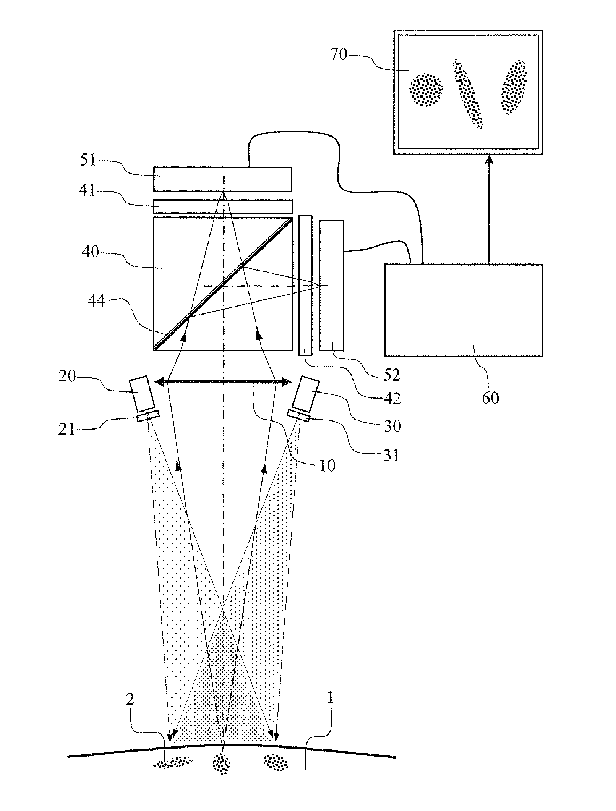
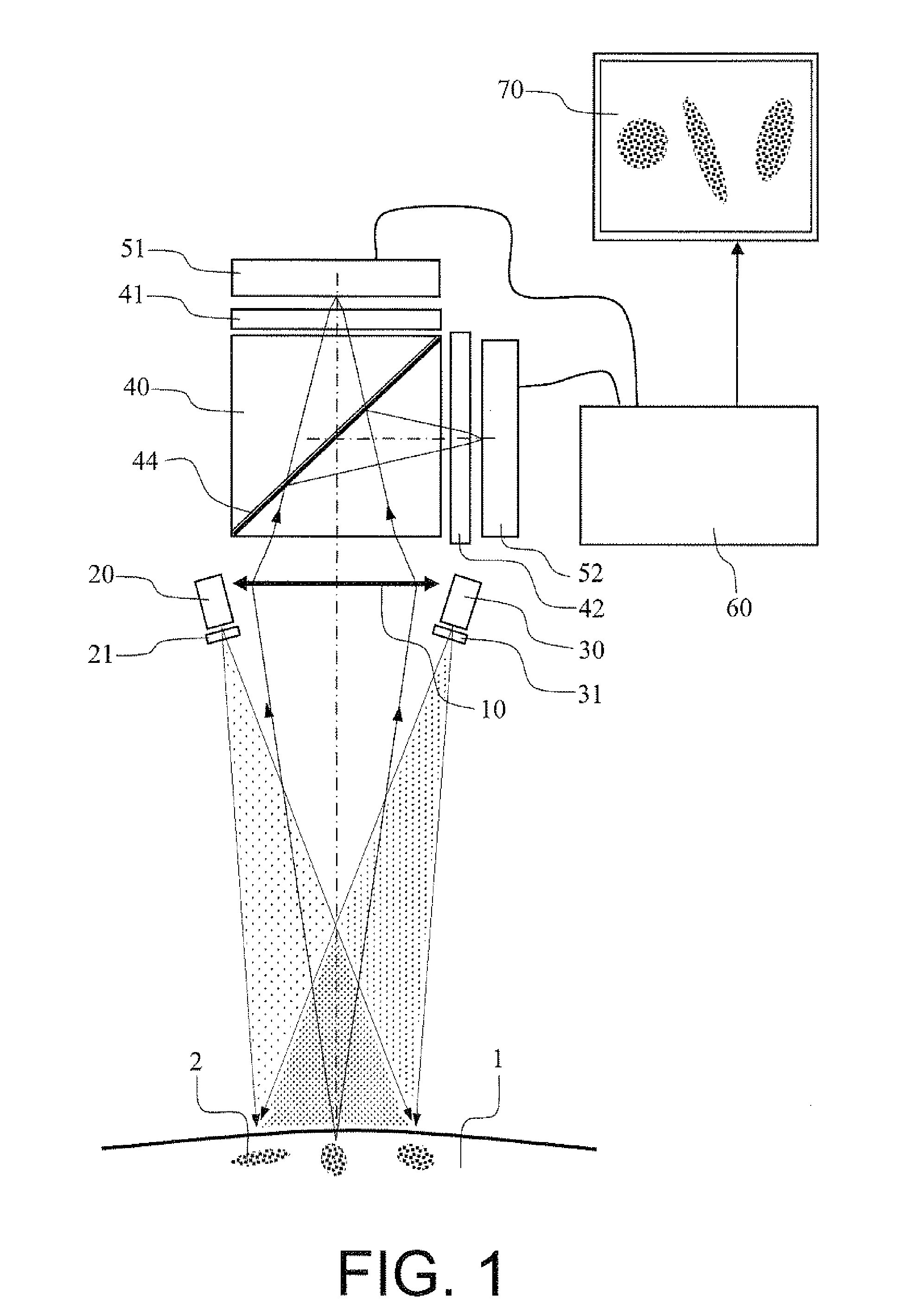
[0050]FIG. 1 represents the diagram of a peroperative optical probe according to this architecture. In this and in the following figures, the dimensions are not necessarily representative of those of a real probe, the objective being to show the general opto-mechanical principles of implantation of the various elements and the route of the light rays through the optical elements. In this and the following figures, neither the mechanical casing surrounding the probe and held by the user nor the various mechanical supports making it possible to maintain and to position the various optical components are represented. The placing of its various elements does not pose any particular difficulties for the person skilled in the art.

[0051]The probe is represented in operational use, that is to say held by an operator above an intervention zone.

[0052]The probe according to the invention essentially comprises:[0053]a first so-called excitation lighting source 20, the spectral radiation of this...

second embodiment

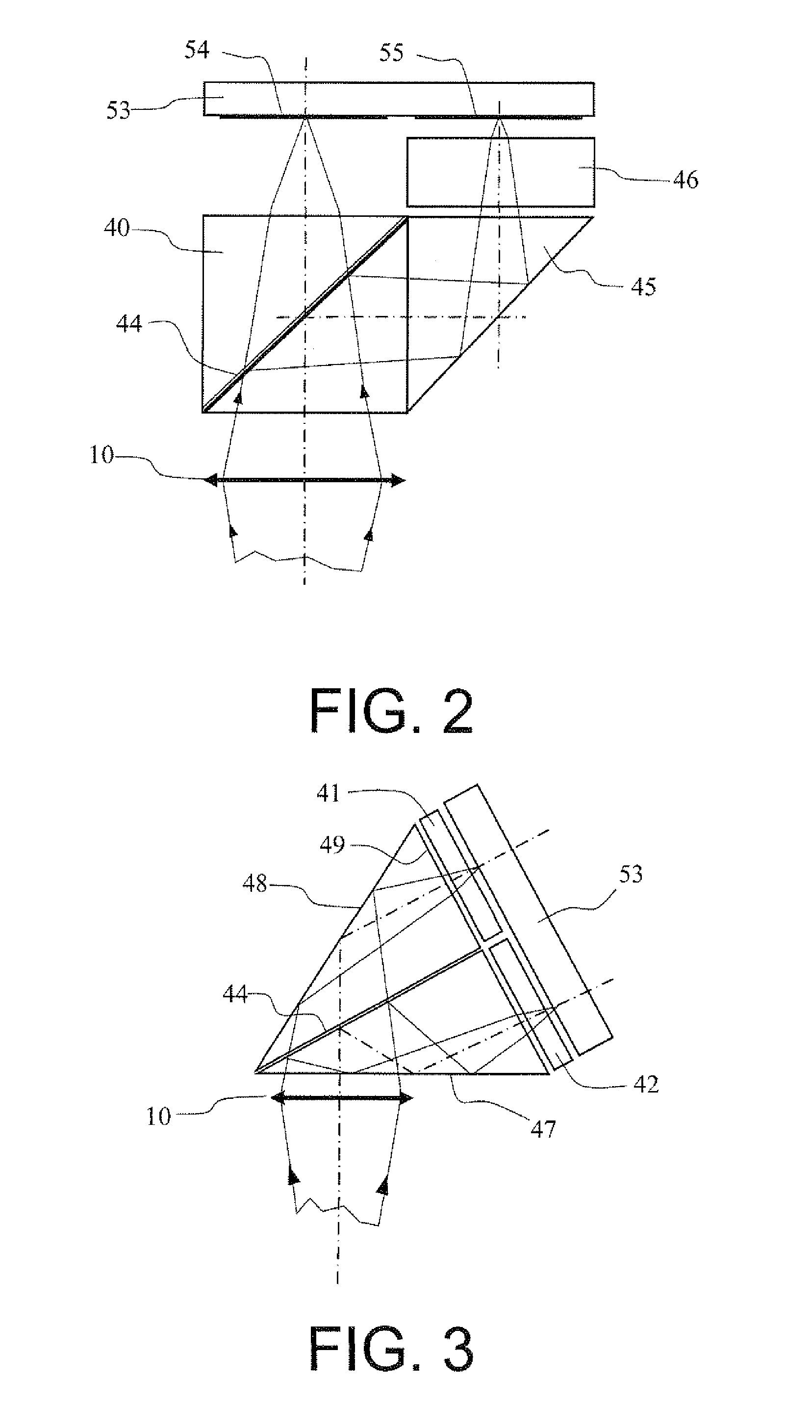
[0065]In a second embodiment represented in FIG. 3, the splitter prism is a “Koster” prism composed of two identical prisms, the face common to the two prisms 44 comprising a dichroic treatment reflecting the visible radiation and transmitting the radiation lying in the near infrared. Each prism has a cross-section of right-angled triangular shape. The propagation of the light rays is as follows: the light rays emanating from the objective 10 enter the “Koster” prism through the lower face 47, are split by the dichroic treatment 44, are reflected by total internal reflection on the faces 47 and 48 and exit at quasi-normal incidence through the face 49 where they may be filtered by the filters 41 and 42 before being focused on the single photosensitive sensor 53.

[0066]As was stated, the excitation sources are generally laser sources powerful enough to cause discernable fluorescence. Hence, it is important to ensure the ocular safety of the operator or of the personnel undertaking the...


PUM


Abstract

Optical probes for medical applications are provided. The probe is devised so as to be able to be held in one hand. A basic version of the probe includes: a first excitation lighting source suitable for causing a fluorescence radiation of predetermined substances; a second visible lighting source, the first and the second source being devised so as to illuminate a common zone termed the intervention zone; a first photosensitive matrix sensor; and a second photosensitive matrix sensor. The first and second photosensitive matrix sensors are devised in such a way that, when the optical probe is arranged a predetermined distance from the intervention zone, the image in the visible spectrum of the said zone is formed on the photosensitive surface of the first matrix sensor and the image in the fluorescence spectrum of the said zone is formed on the photosensitive surface of the second sensor. A first variant of the probe includes only a single optical objective, a second variant only a single photosensitive matrix sensor, and a third variant makes it possible to work under polarized light.

Description

CROSS-REFERENCE TO RELATED APPLICATION[0001]This application claims priority to foreign French patent application No. FR 1000401, filed on Feb. 2, 2010, the disclosure of which is incorporated by reference in its entirety.FIELD OF THE INVENTION[0002]The field of the invention is that of peroperative optical probes used in immunophotodetection techniques. They serve during surgical intervention and notably for the ablation of tumours.BACKGROUND[0003]The technique of immunophotodetection (acronym: IPD) was initiated about ten years ago, notably at the Centre de Recherche et de Lutte contre le Cancer in Montpellier. The principle of this technique consists in injecting into a live body, human being or animal, an antibody-fluorophore conjugate which fixes to cancerous cells through an antibody-antigen reaction. For example, digestive cancers may secrete so-called carcinoembryonic antigens (acronym: CEA) which serve as targets for the antibodies. In the course of the operation, the surge...

Claims


Application Information

Patent Timeline
IPC IPC(8): A61B6/00B65H49/30B65H49/32
CPCA61B5/0059
Inventor PELTIE, PHILIPPEBERGER, MICHEL
Owner COMMISSARIAT A LENERGIE ATOMIQUE ET AUX ENERGIES ALTERNATIVES
Learn More