Thermal storage system for use in connection with a thermal conductive wall structure

Inactive Publication Date: 2011-08-11
ENCON ENVIRONMENTAL CONSTR SOLUTIONS
39 Cites 5 Cited by

AI-Extracted Technical Summary

Problems solved by technology

Heating and cooling buildings consumes a large amount of energy.
However, there has been a lack of construction technology specifically designed to take advantage of the fact that the ground surrounding and underlying a building can b...

Benefits of technology

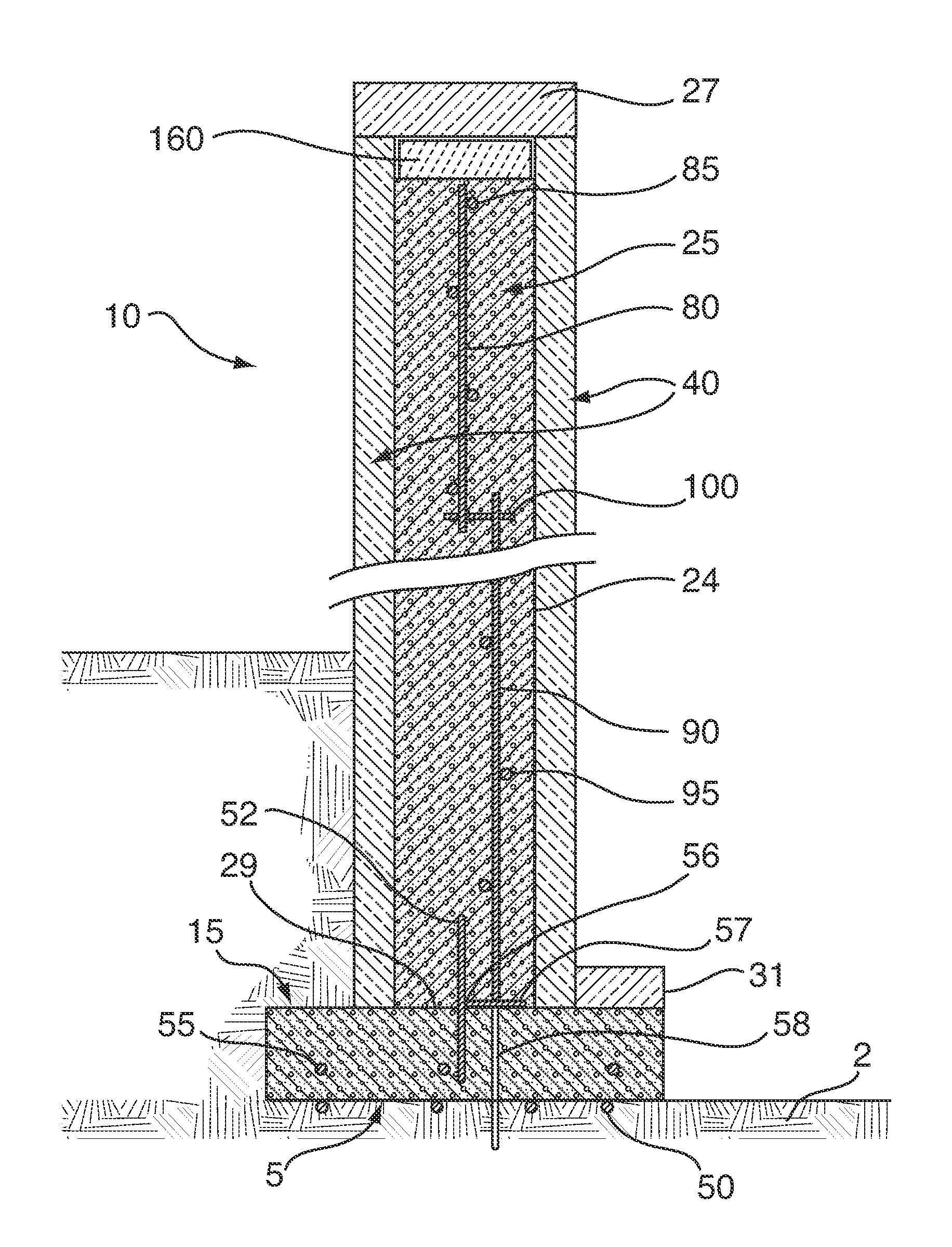
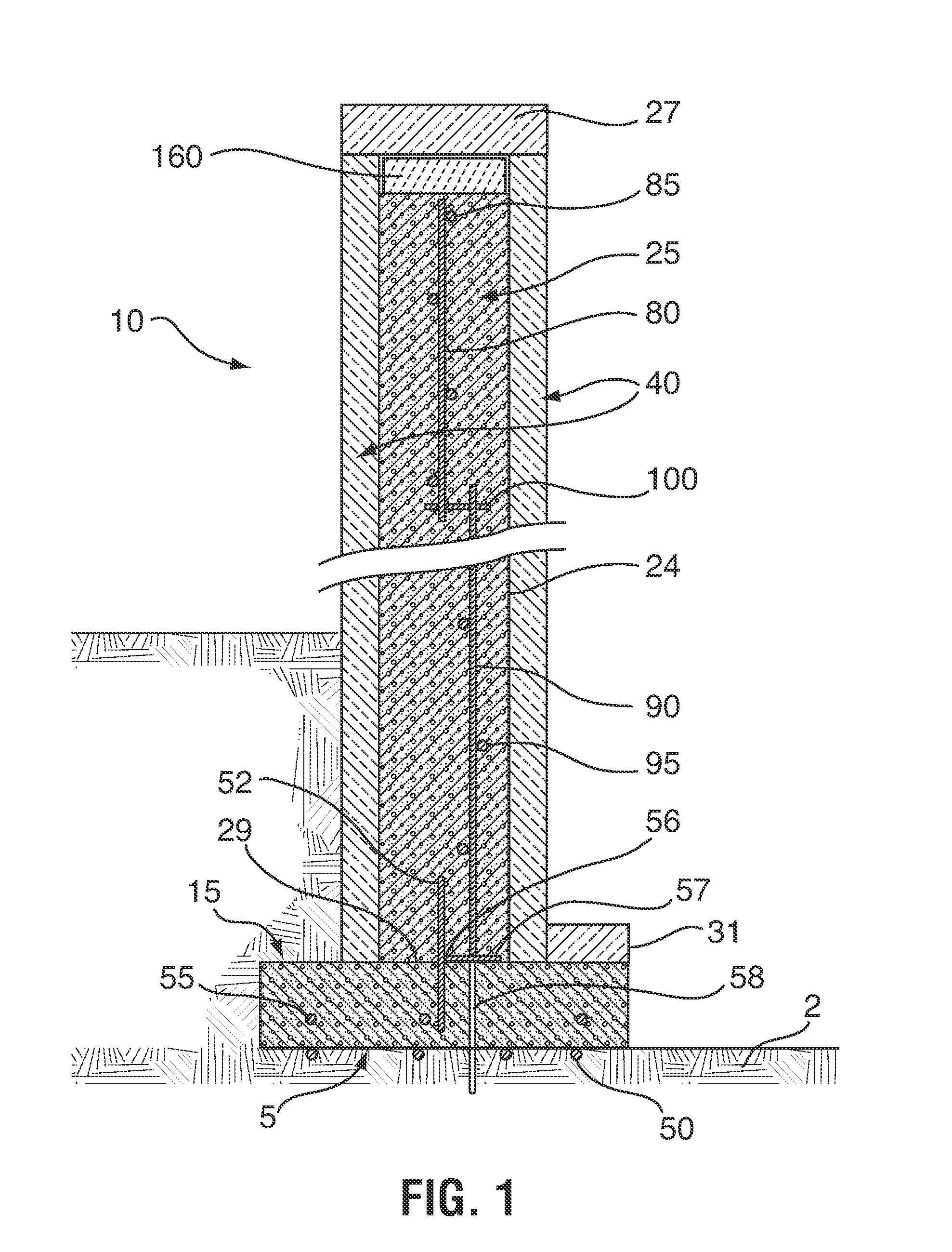
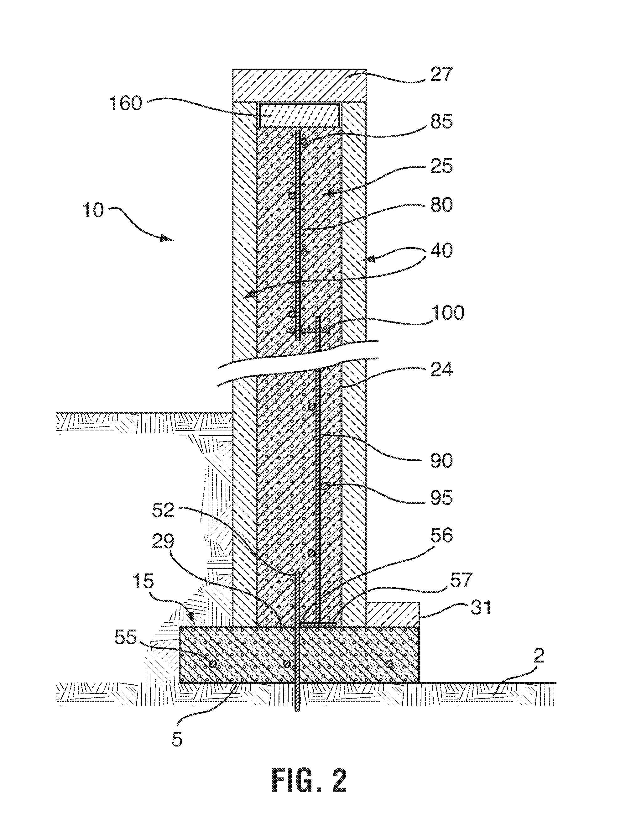
The present invention provides a thermal storage system for storing heat in the ground beneath a building such that the stored heat can be transferred to a thermally conductive ground engaging footing. Therefore, in at least one embodiment, the thermally conductive ground engaging footing can form the below g...

Abstract

There is described a thermal storage system for transferring and storing heat in the ground, the thermal storage system comprising pumping means configured to circulate a working fluid, a heat exchanger, a supply output, a length of pipe, a return inlet and a thermally conductive ground engaging footing such that the pumping means circulates the working fluid through the length of pipe allowing heat transfer between the ground and the working fluid, the thermally conductive ground engaging footing thermally communicating with the ground.

Application Domain

Other heat production devicesHeat storage plants +5

Technology Topic

Thermal energy storageWorking fluid +3

Image

  • Thermal storage system for use in connection with a thermal conductive wall structure
  • Thermal storage system for use in connection with a thermal conductive wall structure
  • Thermal storage system for use in connection with a thermal conductive wall structure

Examples

  • Experimental program(1)

Example

Example
By way of example, the thermal storage system of the present invention was tested using the following input parameters:
Variable Value Unit Comments soil thermal conductivity 1.5 W/mK This value is fixed and estimated for dry soil pipe thermal conductivity 0.51 W/m · K This value is fixed and known for pipe selected inside pipe temperature 80 ° C. This value is fixed and known desired ground temperature 23 ° C. This value is chosen as a set point inside pipe radius 0.013 m This value will depend on pipe selection outside pipe radius 0.019 m This value will depend on pipe selection and is selectable and variable distance from pipe to 1.119 m This value is chosen by installing engineer and footing will depend on application maximum volumetric 2500000 J/m3 · K This value is fixed and estimated for dry soil specific heat of soil minimum volumetric 2000000 J/m3 · K This value is fixed and estimated for dry soil specific heat of soil specific heat of working 3558.8 J/kg · K This value is known for this working fluid fluid (50-50 water/glycol mix) density of working fluid (50-50 1041 kg/m3 This value is known for this working fluid water/glycol mix) conductive heat transfer Calculate W/m This value is calculated based on system temperature loss/meter of Calculate C./m This value is calculated based on system pipe mass flow rate Calculate kg/sec This value is calculated based on system desired soil length 37 m This will depend on building desired length of 74 m This is based on a system with two loops underground piping
Based on the above input parameters, the skilled person in the art can now calculate the conductive heat transfer, the temperature loss from the input of the working fluid to the return of the working fluid, and the necessary mass flow rate for the system, using heat transfer and thermodynamic calculations known in the art, for proper configuration of the system, including the depth the conduits 202 are buried below the lower surface 301 of slab 300, and the horizontal spacing or inset of the conduits from the inner edge of footing 15.
Thermal storage system 200 can be retrofitted to an existing structure by trenching around its periphery for installation of conduits 204/206, or as the case might be, and an insulating barrier over the conduits to perform the function of slab 300 and EPS layer 270.
The above-described embodiments of the present invention are meant to be illustrative of preferred embodiments of the present invention and are not intended to limit the scope of the present invention. Various modifications, which would be readily apparent to one skilled in the art, are intended to be within the scope of the present invention. The only limitations to the scope of the present invention are set out in the following appended claims.

PUM

no PUM

Description & Claims & Application Information

We can also present the details of the Description, Claims and Application information to help users get a comprehensive understanding of the technical details of the patent, such as background art, summary of invention, brief description of drawings, description of embodiments, and other original content. On the other hand, users can also determine the specific scope of protection of the technology through the list of claims; as well as understand the changes in the life cycle of the technology with the presentation of the patent timeline. Login to view more.
Why Eureka
Try Eureka